

Light assembly, method for reducing light loss, vehicle design element and rear view device
- Summary
- Abstract
- Description
- Claims
- Application Information
AI Technical Summary
Benefits of technology
Problems solved by technology
Method used
Image

Examples
Embodiment Construction
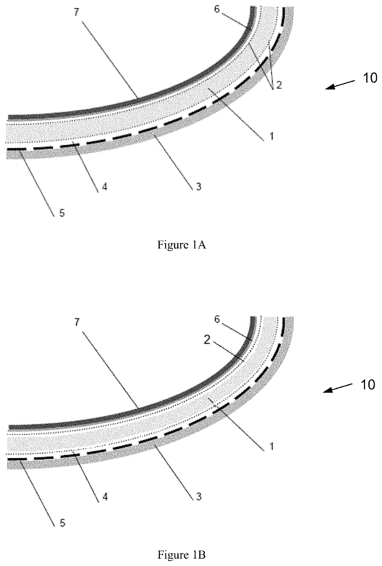
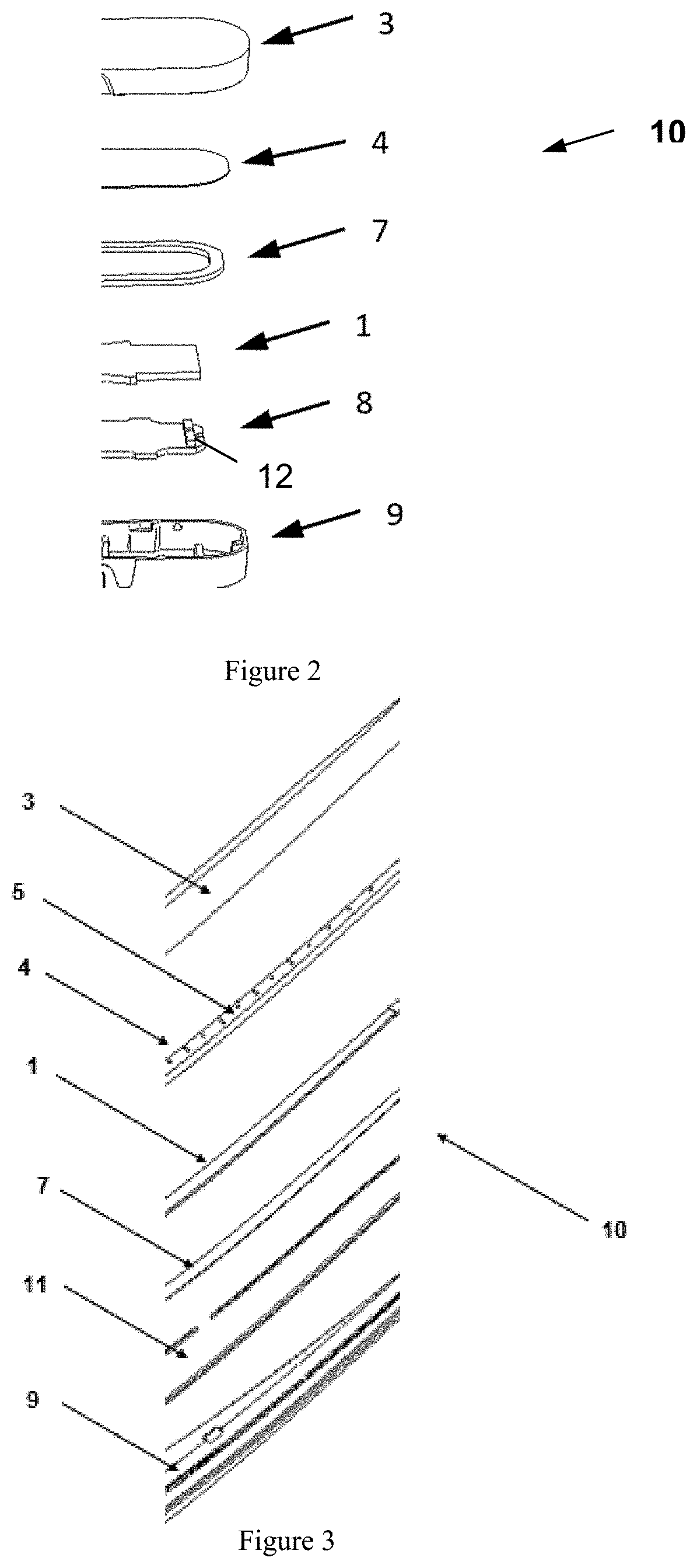
[0056]Referring now to FIG. 1A, there is shown a schematic lighting assembly of a system 10, which has a light pipe 1, a light source, a mask 4 with an image / artwork 5 and a lens 3. The lens 3 comprises a transparent and / or translucent metal layer which, in use, is translucent. The light source is switchable between an on state in which the image 5 is visible on the front surface of the lens 3 and an off state in which no image is visible on the front surface of the lens. The system 10 also encompasses an reflector 6 (such as a white reflector) and a gasket 7.
[0057]According to an example, contact areas 2 are provided on the reflector and on the mask 4 in order to reduce the light loss in the light pipe 1. These small contact areas 2 could also be on the light pipe 1 in addition to the current parts or on both. The system 10 provides light output such that a viewer would see a homogenous annular light output. In the embodiment of FIG. 1A, the small contact areas are shown on the lig...
PUM
 Abstract
Description
Claims
Application Information