
Methods and systems for solar shade analysis

a technology of solar radiation and methods, applied in the field of methods and systems for solar radiation analysis, can solve the problems of device limitations, difficult to make accurate measurements, and limited number of systems that measure solar radiation

Inactive Publication Date: 2012-05-17
ARMAGEDDON ENERGY
View PDF7 Cites 40 Cited by
  • Summary
  • Abstract
  • Description
  • Claims
  • Application Information

AI Technical Summary

Benefits of technology

The invention provides systems and methods for analyzing solar shading. It can be used as a standalone system or as a component of an integrated solution for solar applications. The invention can be seamlessly integrated into existing businesses and processes. It includes a fish-eye lens, compass, and bubble level for leveling the device and capturing fish-eye photographs. The photographs are then analyzed and compared to sun path diagrams to calculate shading percentages at a particular location. The invention can be used with different electronic computing devices and programming languages. The technical effects of the invention include improved solar shading analysis for better design and optimization of solar applications.

Problems solved by technology

A number of systems that measure solar radiation may have limitations in their ease of use and accuracy.
Many have alignment problems that make it difficult to make accurate measurements.
Further, devices may have limitations that include the lack of image calibration, the need to determine coordinates that uniquely identify the location of the device on the earth or region, the need to be left on-site for a long period of time, an inability to identify the skyline and open sky, and / or an inability to account for shading.
In addition, the devices may be expensive to manufacture and / or use.
For example, the Solmetric SunEye and Wiley Electronics ASSET are specialized electronic devices that provide sophisticated shade analysis but are expensive, at $1,500 and $600 respectively at the time of filing of this application.
In addition to high cost, many existing approaches and tools may require training and careful application, may require extra coordination such as keeping the device level with a compass arrow correctly aligned while attempting to press a button to take a picture, and may be difficult to use in actual field conditions such as on a sloped roof and in a bright sun.

Method used


Image

  • Methods and systems for solar shade analysis
  • Methods and systems for solar shade analysis
  • Methods and systems for solar shade analysis

Examples


first embodiment

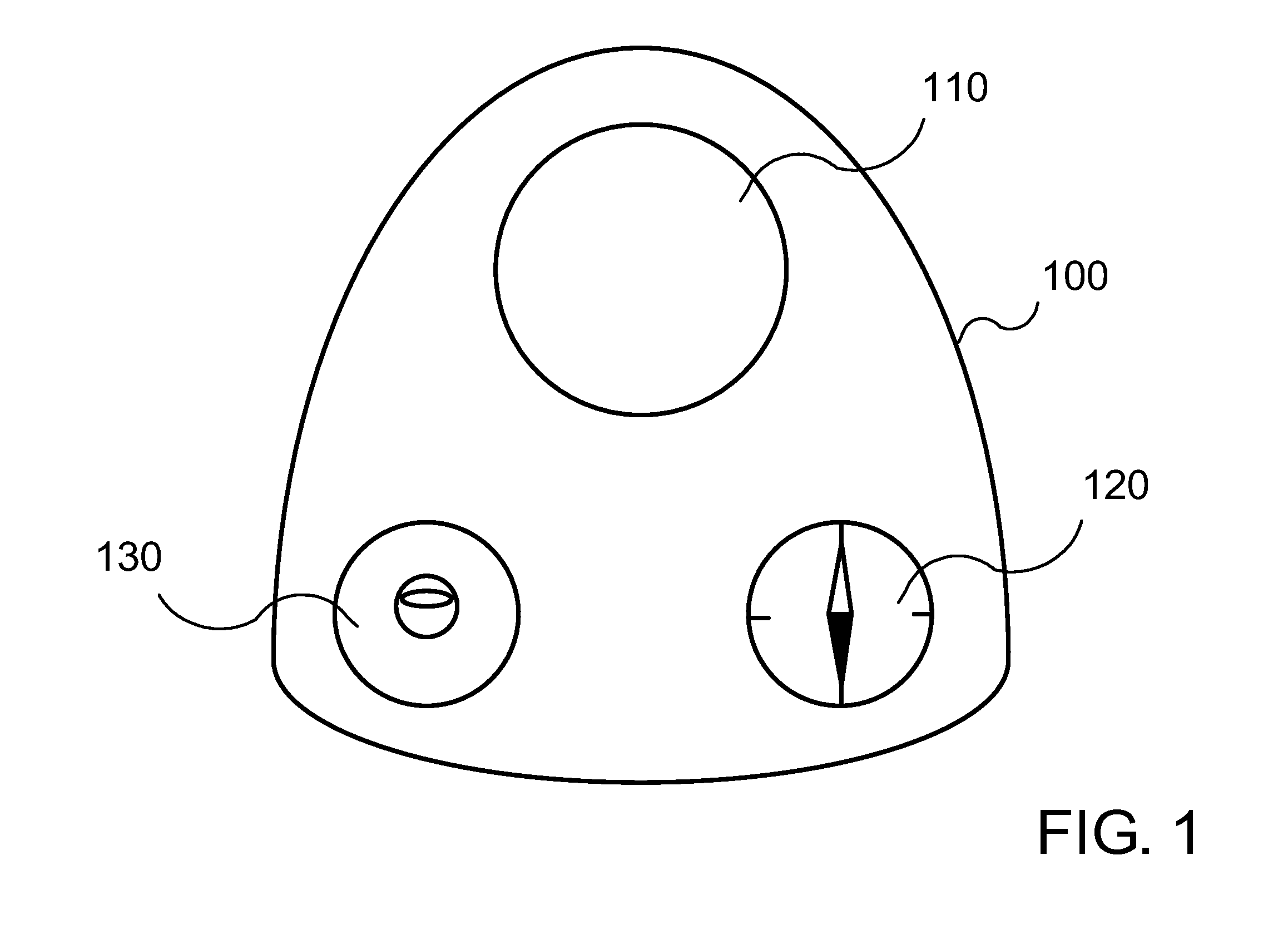
[0032]Referring to FIG. 1, in a first embodiment, the solar shading analysis device may include a fish-eye lens 110 that is placed on a platform 100. The fish-eye lens may be made of plastic or some other material. A level 130, such as a bubble level, may also be placed on the platform 100. Further, the platform 100 may also hold a compass 120. The platform may also be made of plastic and have some kind of adhesive backing. FIG. 1 shows one embodiment of the solar shading analysis device from a bird's eye view.

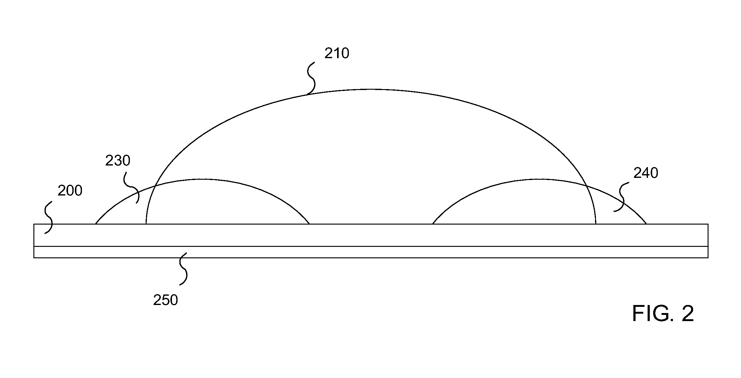
[0033]FIG. 2 shows one example of a side view of a first embodiment of the solar shading analysis device. A fish-eye lens 210, a level such as a bubble level 230 and a compass 240 may be included and placed on a platform 200. As can be seen in FIG. 2, the platform 200 may have some kind of adhesive backing 250.

[0034]Referring to FIG. 3, the solar shading analysis device may be placed over the lens of a built-in camera 340 of a mobile phone (or other device with a camera) 350. ...

second embodiment

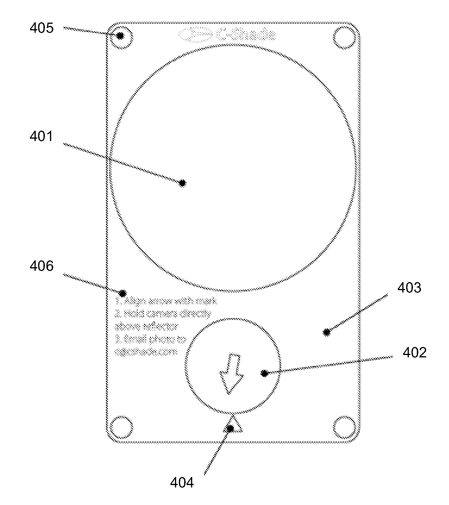
[0037]Referring to FIG. 5, one embodiment of a user's interaction with the solar shading device is shown. A person using the device 501 may place the solar shading device 502 on the surface of a roof 503, or in another location where solar shading analysis is required. The device 502 may be oriented so that the compass arrow is pointing in the general direction of the mark and towards the user 501. The user 501, while standing above the device 502 and keeping the camera phone 504 directly above the device 502, may take a photo of the device 502.

[0038]In order to accurately calculate solar availability using the solar shading device 502, the camera must be level and as close as possible to directly above the device 502 such that a plumb line from the camera lens would go through the center of the device. The natural sense of balance of the user will keep the user's body positioned so that the camera will be close to the required position if the user is instructed to keep the device c...


PUM

PropertyMeasurementUnit
transparentaaaaaaaaaa
self-adhesiveaaaaaaaaaa
magneticaaaaaaaaaa

Abstract

A device for performing solar shade analysis combines a spherical reflective dome and a ball compass mounted on a platform, with a compass alignment mark and four dots in the corners of the platform. A user may place the device on a surface of a roof, or in another location where solar shading analysis is required. A user, while standing above the device can take a photo of the device. The photographs can then be used in order to evaluate solar capacity and perform shade analysis for potential sites for solar photovoltaic systems. By using the device in conjunction with a mobile device having a camera, photographs may be taken and uploaded, to be analyzed and processed to determine a shading percentage. For example, the solar shade analysis system may calculate the percentage of time that the solar photovoltaic system might be shaded for each month of the year. These measurements and data, or similar measurements and data, may be valuable when applying for solar rebates or solar installation permits.

Description

CROSS-REFERENCE[0001]This application claims the benefit of U.S. Provisional Application No. 61 / 138,069, filed Dec. 16, 2008, which application is incorporated herein by reference in its entirety.BACKGROUND[0002]There is a constant need for energy to power the growing energy consumption needs of our modern society. At present, fossil fuels are the main source of this energy but factors such as fossil fuel scarcity, resultant pollution from burning fossil fuels, and geopolitical factors that affect the price and availability of fossil fuels have resulted in a need for alternative sources of energy. An example of a popular form of an alternative energy source is solar energy.[0003]In order to utilize solar energy, solar energy systems have been created and designed to harness received solar radiation into thermal or electrical energy through various means. These solar energy systems typically include a solar energy collector to collect the solar radiation and other components that may...

Claims


Application Information

Patent Timeline
Patent Type & Authority Applications(United States)
IPC IPC(8): G06K9/00G01N21/01H04N5/225F24S50/20
CPCY02E10/52Y02B10/20G06K9/00771F24J2200/04G01W1/12G06K9/3216H02S50/00F24J2/4607G06K2009/3225H04N7/183Y02B10/12G06K9/22F24S2201/00Y02E10/50Y02B10/10G06V20/52
Inventor DIMOV, DMITRY
Owner ARMAGEDDON ENERGY
Learn More