Foldable Safety Handrail Assembly

a safety handrail and folding technology, applied in the direction of fencing, building types, constructions, etc., can solve the problems of inconvenience for users, achieve the effect of convenient and quick unlocked and folded, increased strength and stiffness, and easy deformation

Active Publication Date: 2012-05-24
YUH INST CO LTD
View PDF21 Cites 5 Cited by
  • Summary
  • Abstract
  • Description
  • Claims
  • Application Information

AI Technical Summary

Benefits of technology

[0010]According to the primary advantage of the present invention, the user only needs to push the push knob or pull the pull knob to unlock and fold the rail so that the rail can be unlocked and folded easily and quickly, thereby facilitating the user unlocking and folding the rail in an energy-saving manner.
[0011]According to another advantage of the present invention, the control member has a greater strength and stiffness so that the control member will not be easily deformed, worn out or broken during a long-term utilization, thereby enhancing the lifetime of the foldable safety handrail assembly.
[0012]Further benefits and advantages of the present invention will become apparent after a careful reading of the detailed description with appropriate reference to the accompanying drawings.BRIEF DESCRIPTION OF THE SEVERAL VIEWS OF THE DRAWING(S)
[0013]FIG. 1 is a perspective view of a foldable safety handrail assembly in accordance with the preferred embodiment of the present invention.
[0014]FIG. 2 is an exploded perspective view of the foldable safety handrail assembly as shown in FIG. 1.
[0015]FIG. 3 is a partially top cross-sectional view of the foldable safety handrail assembly as shown in FIG. 1.

Problems solved by technology

However, the user has to use a hand tool to screw or unscrew the fastening bolt 55 so as to clamp or loosen the pivot tube 51, thereby causing inconvenience to the user.

Method used


Image

  • Foldable Safety Handrail Assembly
  • Foldable Safety Handrail Assembly
  • Foldable Safety Handrail Assembly

Examples


Embodiment Construction

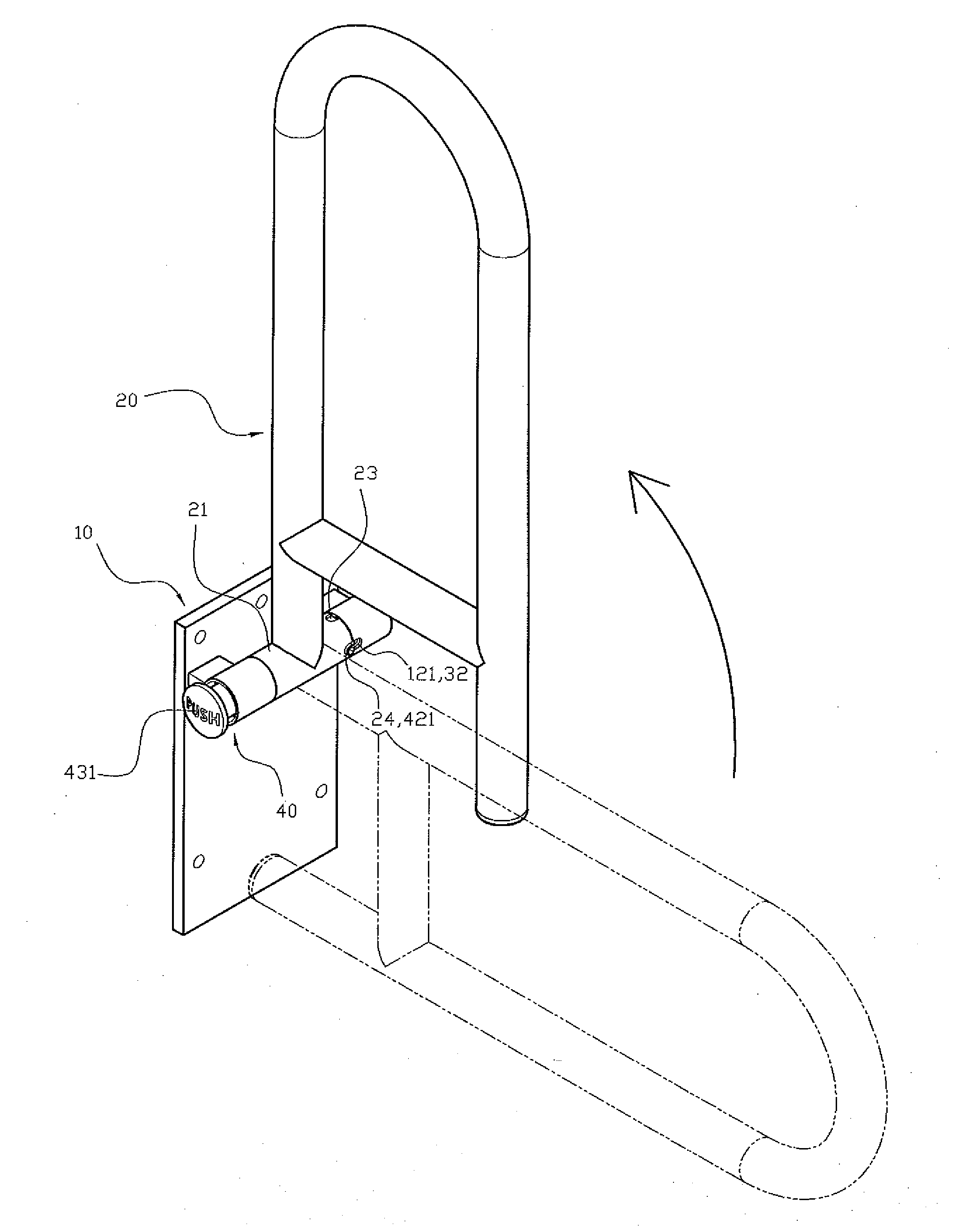
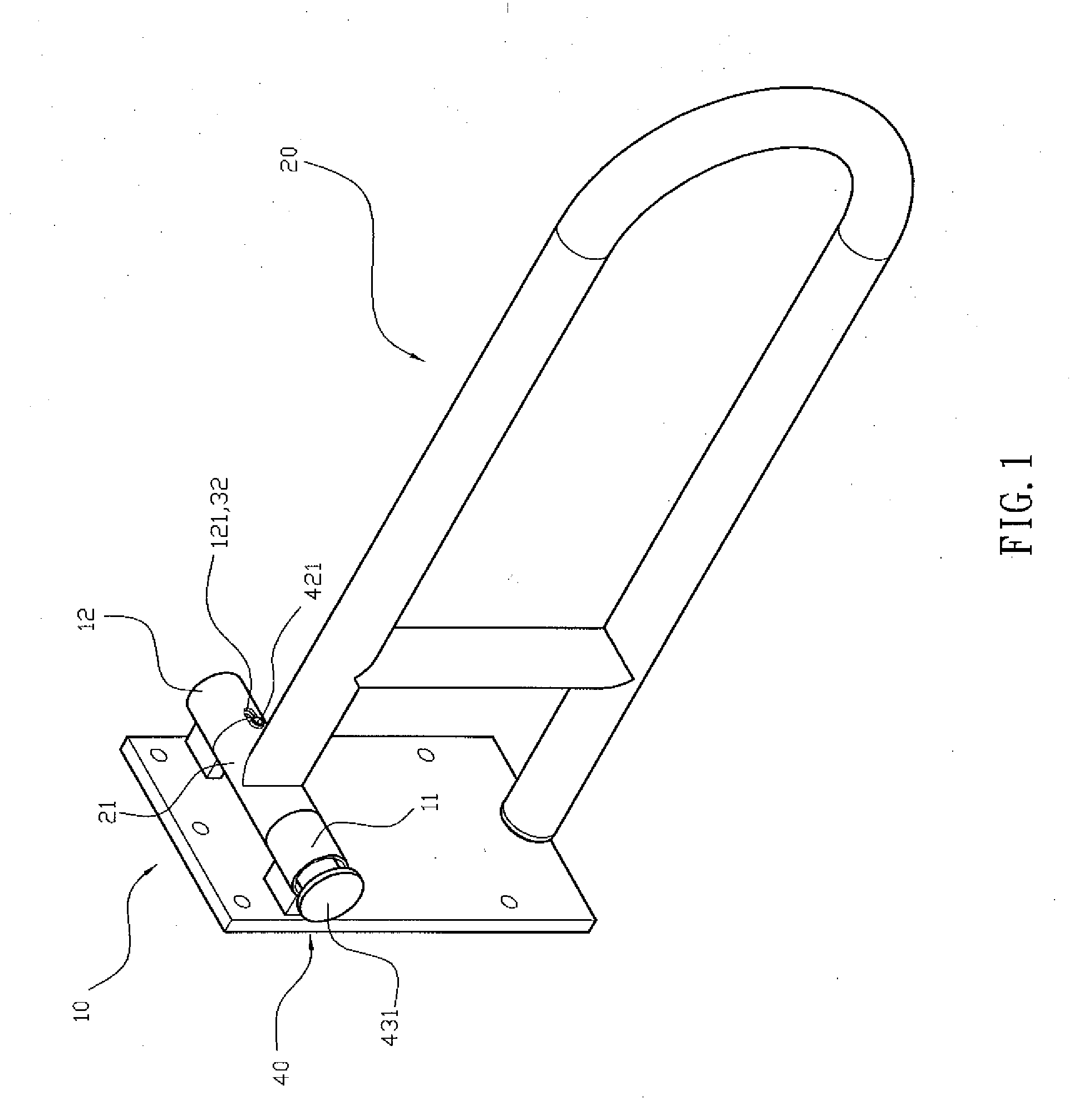
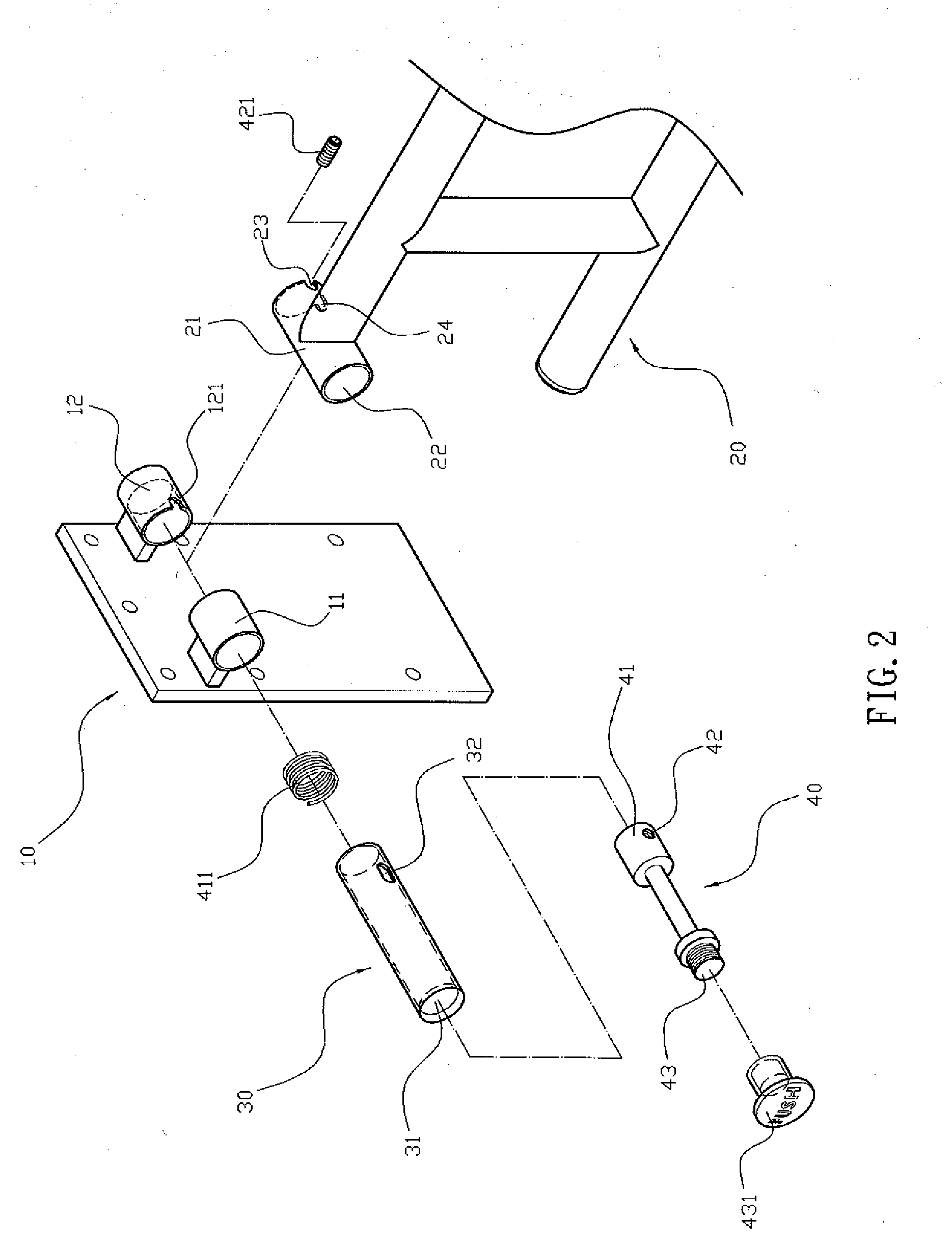
[0024]Referring to the drawings and initially to FIGS. 1-6, a foldable safety handrail assembly in accordance with the preferred embodiment of the present invention comprises a mounting bracket 10 attached to a surface, such as a wall and the like, a fixing sleeve 11 mounted on the mounting bracket 10, a release sleeve 12 mounted on the mounting bracket 10 and having a periphery provided with a release groove 121, a rail 20 pivotally connected with the mounting bracket 10 and having a side provided with a pivot tube 21 which is pivotally mounted between the fixing sleeve 11 and the release sleeve 12 and has a periphery provided with a first locking groove 23 and a second locking groove 24, a locking tube 30 extending through the fixing sleeve 11, the pivot tube 21 and the release sleeve 12 and having a periphery provided with an elongate limit slot 32, a locking member 421 slidably mounted in the limit slot 32 of the locking tube 30 and detachably locked in the first locking groove ...


PUM


Abstract

A foldable safety handrail assembly includes a mounting bracket, a fixing sleeve mounted on the mounting bracket, a release sleeve mounted on the mounting bracket and having a release groove, a rail having a pivot tube which has a first locking groove and a second locking groove, a locking tube extending through the fixing sleeve, the pivot tube and the release sleeve and having a limit slot, a locking member mounted in the limit slot and detachably locked in the first locking groove or the second locking groove, a control member mounted in the locking tube to move the locking member, and a push knob mounted on and pushing the control member. Thus, the user only needs to push the push knob to unlock and fold the rail so that the rail can be unlocked and folded easily and quickly.

Description

BACKGROUND OF THE INVENTION[0001]1. Field of the Invention[0002]The present invention relates to a handrail assembly and, more particularly, to a foldable safety handrail assembly.[0003]2. Description of the Related Art[0004]A conventional foldable safety handrail assembly in accordance with the prior art shown in FIGS. 10 and 11 comprises a mounting bracket 60 attached to a surface, such as a wall and the like, two support tubes 61 mounted on the mounting bracket 60 and spaced from each other, a rail 50 pivotally connected with the mounting bracket 60 and having a side provided with a pivot tube 51 which is pivotally mounted between the two support tubes 61 and has a periphery provided with a first locking hole 511, a locking tube 62 extending through the two support tubes 61 and the pivot tube 51 of the rail 50 and having a periphery provided with a second locking hole 63 aligning with the first locking hole 511 of the pivot tube 51, and an elastic plate 64 mounted in the locking ...

Claims


Application Information

Patent Timeline
Patent Type & Authority Applications(United States)
IPC IPC(8): E04F11/18
CPCY10T403/32344E06B11/023Y10T403/32377E06B11/085
Inventor LIN, YONG-HAO
Owner YUH INST CO LTD
Why Eureka
Try Eureka