Topography device for a surface of a substrate

Inactive Publication Date: 2012-05-24
BOBST SA
View PDF9 Cites 12 Cited by
  • Summary
  • Abstract
  • Description
  • Claims
  • Application Information

AI Technical Summary

Benefits of technology

[0017]By virtue of the topography device defined in Claim 1, it is possible to determine the topography of a surface of a substrate thereby making it possible to detect, to register and to characterize reliefs on the surface o

Problems solved by technology

On the other hand, these solutions are incapable of checking the proper formation of the reliefs.
Solutions using matrix array cameras exist but these

Method used


Image

  • Topography device for a surface of a substrate
  • Topography device for a surface of a substrate
  • Topography device for a surface of a substrate

Examples


Example

BEST WAY OF CARRYING OUT THE INVENTION

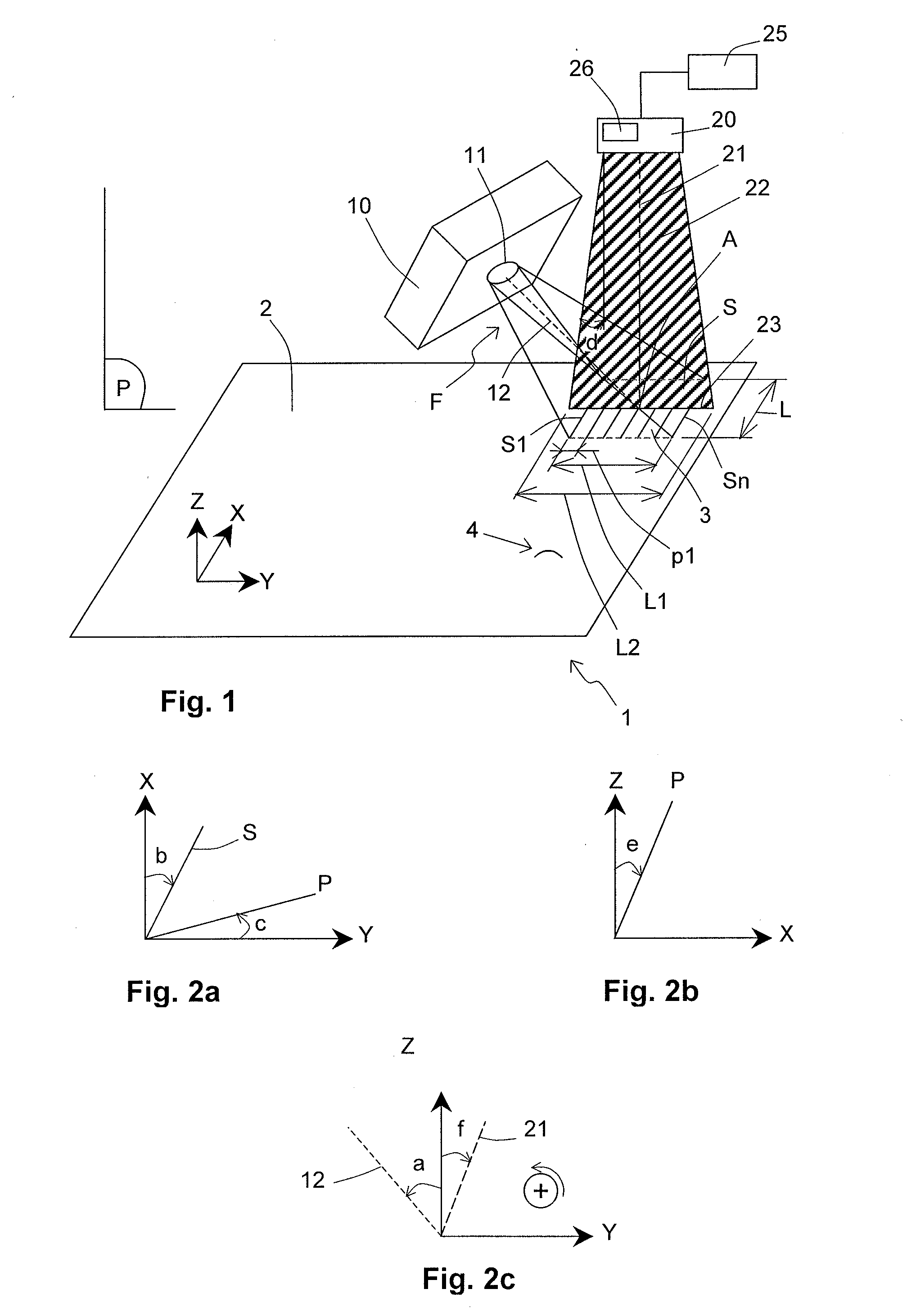
[0026]In the drawing of FIG. 1 has been schematically represented the topography device implemented for the measurement of three-dimensional characteristics of reliefs present on the surface 2 of a cardboard substrate 1 traveling along a substantially plane trajectory of axis X. The plane containing the plane portion of the surface 2 of the substrate 1, that is to say the portion devoid of any relief, is called the reference plane. Axes Y and Z define with the X axis an orthonormal reference of the space in which the reference plane is parallel to the XY plane.

[0027]The device comprises a light source 10 able to project obliquely, through an exit pupil 11, onto the surface 2 of the substrate 1, a light beam F adapted for forming a structured lighting according to a determined illumination profile. Preferably, the light source 10 comprises a coherent light source, typically a laser. Advantageously, the structured lighting is obtained by laser int...


PUM


Abstract

A device for analyzing the topography of a surface (2) of a substrate (1) travelling on a substantially planar course with axes X, Y and Z defining an orthonormal frame of reference of the space. The surface (2) is substantially parallel to the plane XY. A device (10) for structured lighting of the surface (2) engages with a device (20) for measuring light backscattered by the surface (2) in order to analyze topography of the surface(2) during travel of the substrate (1). The lighting device (10) projecting a light beam (F) with an angle of incidence ‘a’ onto the surface (2), to form a plurality ‘n’ of luminous streaks (S1, S2, . . . Sn) thereon. Each luminous streak (S) forms an angle ‘b’ with the axis X1. The measurement device (20) includes a linear camera located in a plane P secant to the plane XY and the plane XZ, the intersection of the plane P with the plane XY forming angles.

Description

TECHNICAL DOMAIN[0001]The present invention relates to a topography device for a surface of a substrate used for the manufacture of packaging.[0002]The invention also relates to a method for the implementation of the topography device according to the invention.[0003]The invention relates finally to a folding-gluing machine comprising a topography device according to the invention.PRIOR ART[0004]To manufacture, for example, a medicine box, it is known to transform a plate element of low density by passing it through various machines. A cardboard sheet is an example of a plate element of low density.[0005]A first known conversion is the printing of a cardboard sheet. This operation consists in depositing or in projecting drops of ink onto a face of the sheet.[0006]A second known conversion is the cutting of a cardboard sheet. This operation consists in cutting shapes from said sheet. The cut shapes are called cutouts or blanks. Creasing are also carried out in the blanks so as to del...

Claims


Application Information

Patent Timeline
IPC IPC(8): G01B11/02B31B1/00G01B11/24B31B50/88
CPCB31B1/74B31B1/88G01B11/2441B31B2201/95B31B2201/88B31B50/006B31B50/88B31B50/74
Inventor PILLOUD, FRANCISRICHARD, MATTHIEUROSSET, BENO T
Owner BOBST SA
Why Eureka
Try Eureka