Centrifugal separator

a centrifugal separator and centrifugal separator technology, applied in the direction of centrifuges, material weighing, instruments, etc., can solve the problems of not being able to achieve normal centrifugation work, taking a long time for pretreatment work,

Inactive Publication Date: 2012-05-24
HITACHI HIGH-TECH CORP
View PDF7 Cites 77 Cited by
  • Summary
  • Abstract
  • Description
  • Claims
  • Application Information

AI Technical Summary

Benefits of technology

[0016]As described above, the present invention can control the symmetric buckets during centrifugal separation to a level constantly equal to or less than a permissible unbalanced weight difference. Therefore, weight adjustment means such as a dummy rack or the like becomes unnecessary.

Problems solved by technology

It takes much time for engagement in such pretreatment work in total examination working hours.
Since, in such a case, malfunction occurs in rotor rotation and so normal centrifugation work cannot be achieved, it is necessary to perform weight adjustment for buckets before the buckets are mounted on the rotor.

Method used


Image

  • Centrifugal separator
  • Centrifugal separator
  • Centrifugal separator

Examples


Embodiment Construction

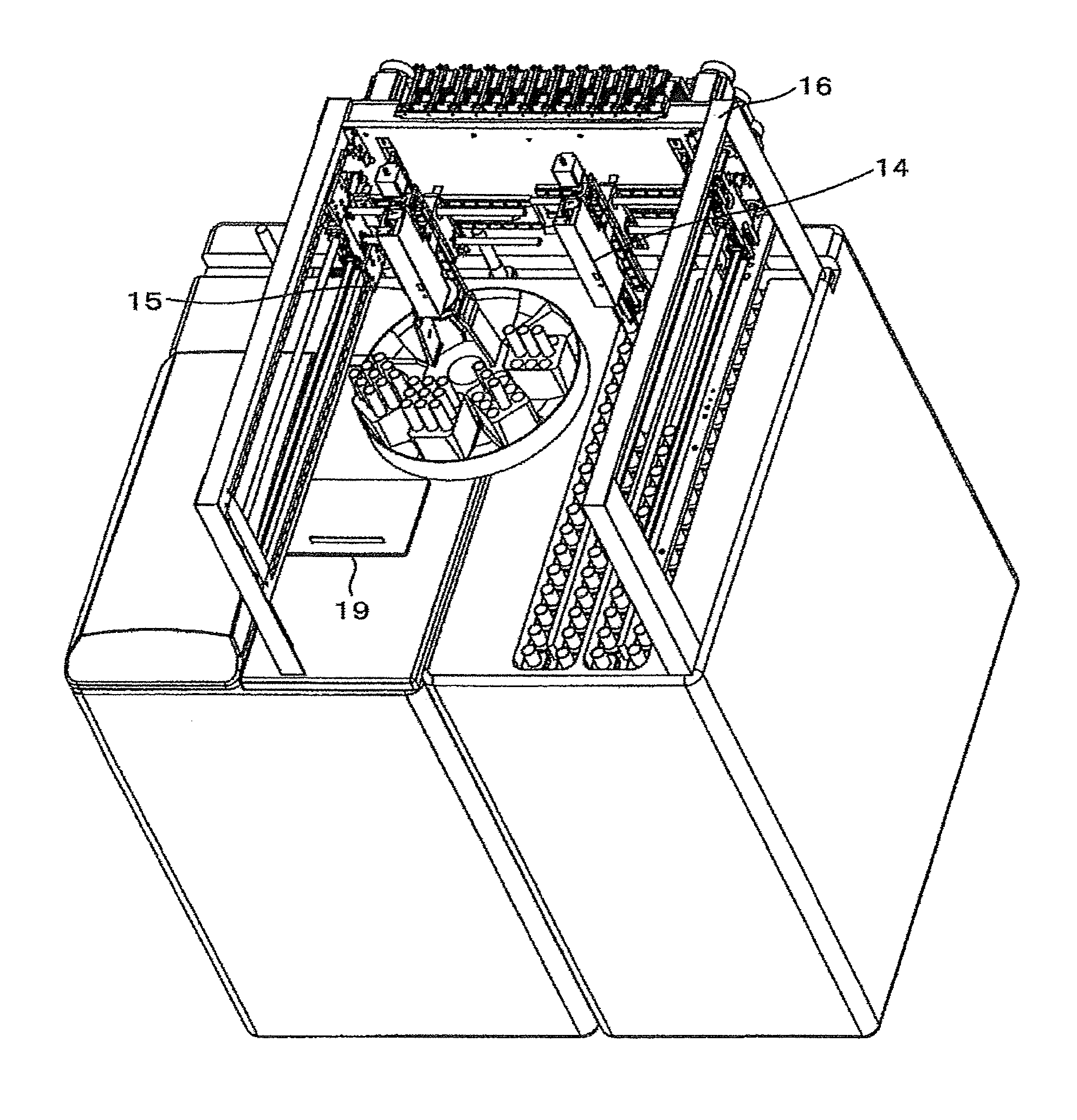
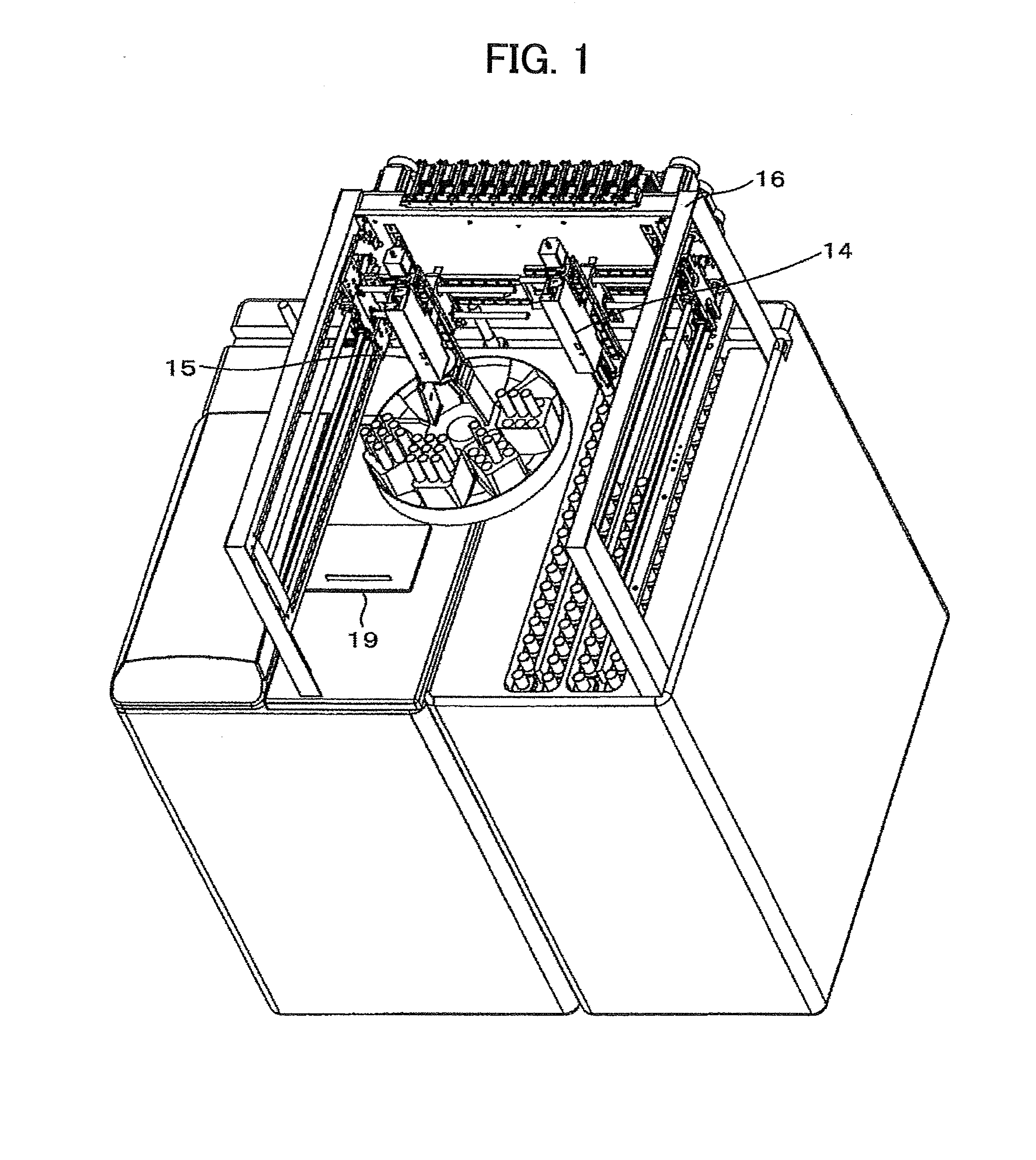
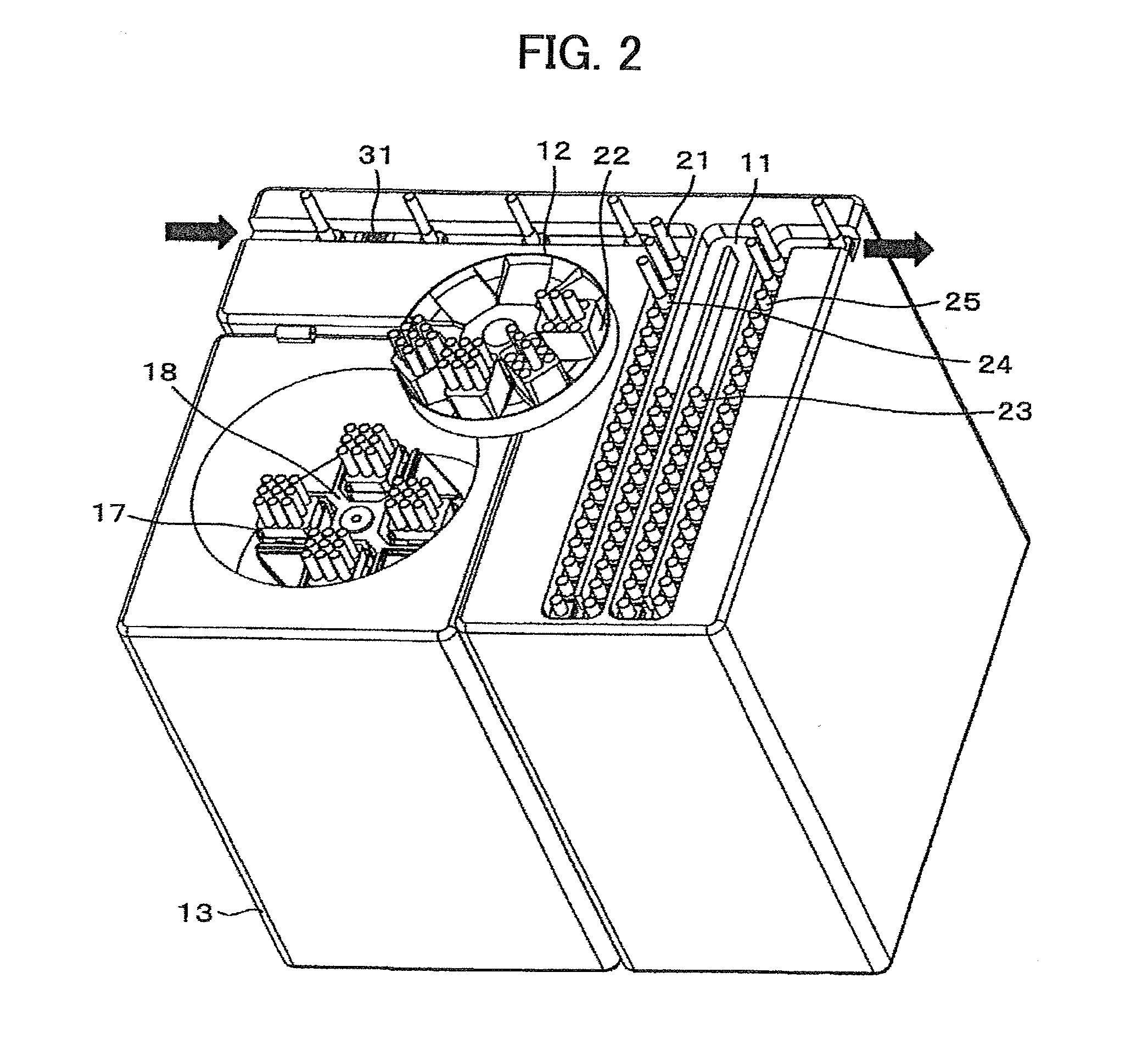
[0020]FIG. 1 is a perspective view of an overall configuration of a centrifuging portion according to the present invention. FIG. 2 is a perspective view illustrating the centrifuging portion with its upper portion removed. FIG. 3 is a flowchart for control operation.

[0021]The centrifuging portion includes, as main constituent elements, a centrifugal buffer line 11 where a plurality of samples 21 are made temporarily standby; a turn table 12 for holding adaptors 22; and a centrifuge 13 for subjecting samples to centrifugal separation.

[0022]Referring to FIG. 2, samples 21 supported by respective holders 23 are sequentially carried into a centrifugal buffer line 11 one by one by a belt line from a previous step unit. The holders 23 are each configured to erectly hold a single sample 21 and are given respective unique ID numbers. A load cell 31 for weight measurement is disposed close to the carrying-in position of the centrifugal buffer line, at which the weight is measured. Weight me...


PUM


Abstract

The weight difference is limited between buckets (17) mounted at respective symmetrical positions with respect to a centrifugal separation rotational center and examination of samples is continuously performed in the order in which they are received. In particular, when a sample (21) is carried in a centrifugal buffer line (11), its weight is measured by weight measuring means (31). It is assumed that the names of two adaptors (22) placed at respective symmetrical positions with respect to the centrifugal separation rotational center are defined as an adaptor A and an adaptor B. A first sample is put on the adaptor A and a second sample is put on the adaptor B. Then, a third sample and subsequent ones are each put on the adaptor (22) lighter than the other adaptor after the total weights of samples put on the adaptors are computation-compared with each other.

Description

TECHNICAL FIELD[0001]The present invention relates to centrifugal separators for subjecting samples to centrifugal separation. In particular, the invention relates to a centrifugal separator that can avoid unbalanced operation attributable to a difference in weight during centrifugal separation.BACKGROUND ART[0002]Laborsaving for examination work in the medical field has recently proceeded by introducing various types of automatic equipment. For the examination in a hospital, the samples for test of inpatients and outpatients are collected from departments in the hospital and collectively processed in an examination room. Examination items for each sample are sent from doctors to the examination room by use of an online information processing system. Results of the examination are then reported online from the examination room to the doctors.[0003]For many of examination items on blood or urine, pretreatment for examination needs to be performed such as centrifugal separation, unplu...

Claims


Application Information

Patent Timeline
Patent Type & Authority Applications(United States)
IPC IPC(8): B04B5/02B04B13/00B04B15/00
CPCB04B2011/046G01N2035/00495G01N35/00029G01N5/00
Inventor FUKUGAKI, TATSUYAOGA, HIROSHIOBA, SHIGEMIISOBE, TETSUYAONIZAWA, KUNIAKI
Owner HITACHI HIGH-TECH CORP
Why Eureka
Try Eureka