Light trapping optical cover

a technology of optical cover and light trapping, which is applied in the direction of discharge tube/lamp details, biomass after-treatment, lens, etc., can solve the problems of increased system dimensions, material consumption, weight and cost, and achieve the effect of increasing the optical path length of light rays and enhancing the useful light absorption of the devi

Active Publication Date: 2012-05-31
S V V TECH INNOVATIONS
View PDF8 Cites 17 Cited by
  • Summary
  • Abstract
  • Description
  • Claims
  • Application Information

AI Technical Summary

Benefits of technology

[0010]The present invention solves a number of light harvesting problems within a compact system utilizing efficient light deflection and trapping mechanisms. An optically transparent layer is provided which can be placed on top of a light harvesting device and enhance the useful light absorption in the

Problems solved by technology

However, this results in the increased system di

Method used


Image

  • Light trapping optical cover
  • Light trapping optical cover
  • Light trapping optical cover

Examples


Embodiment Construction

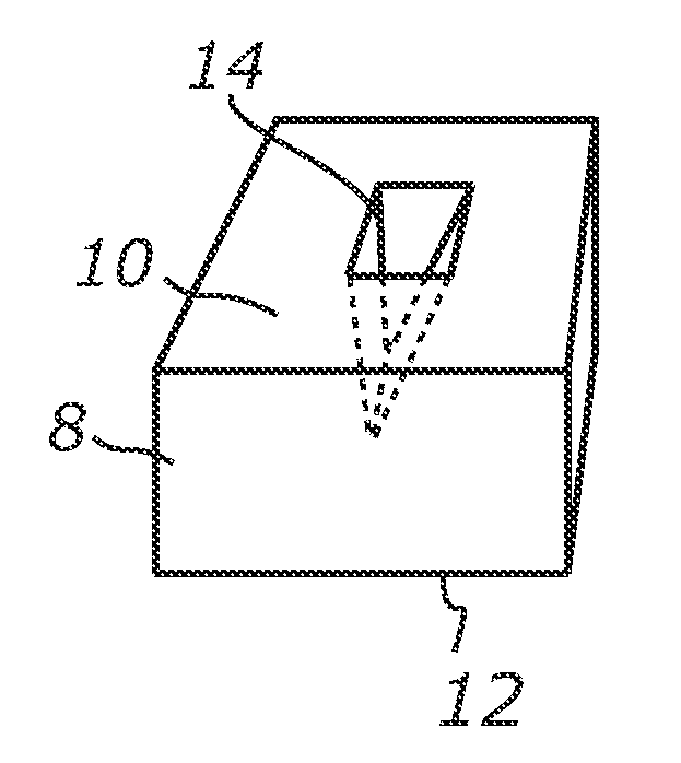
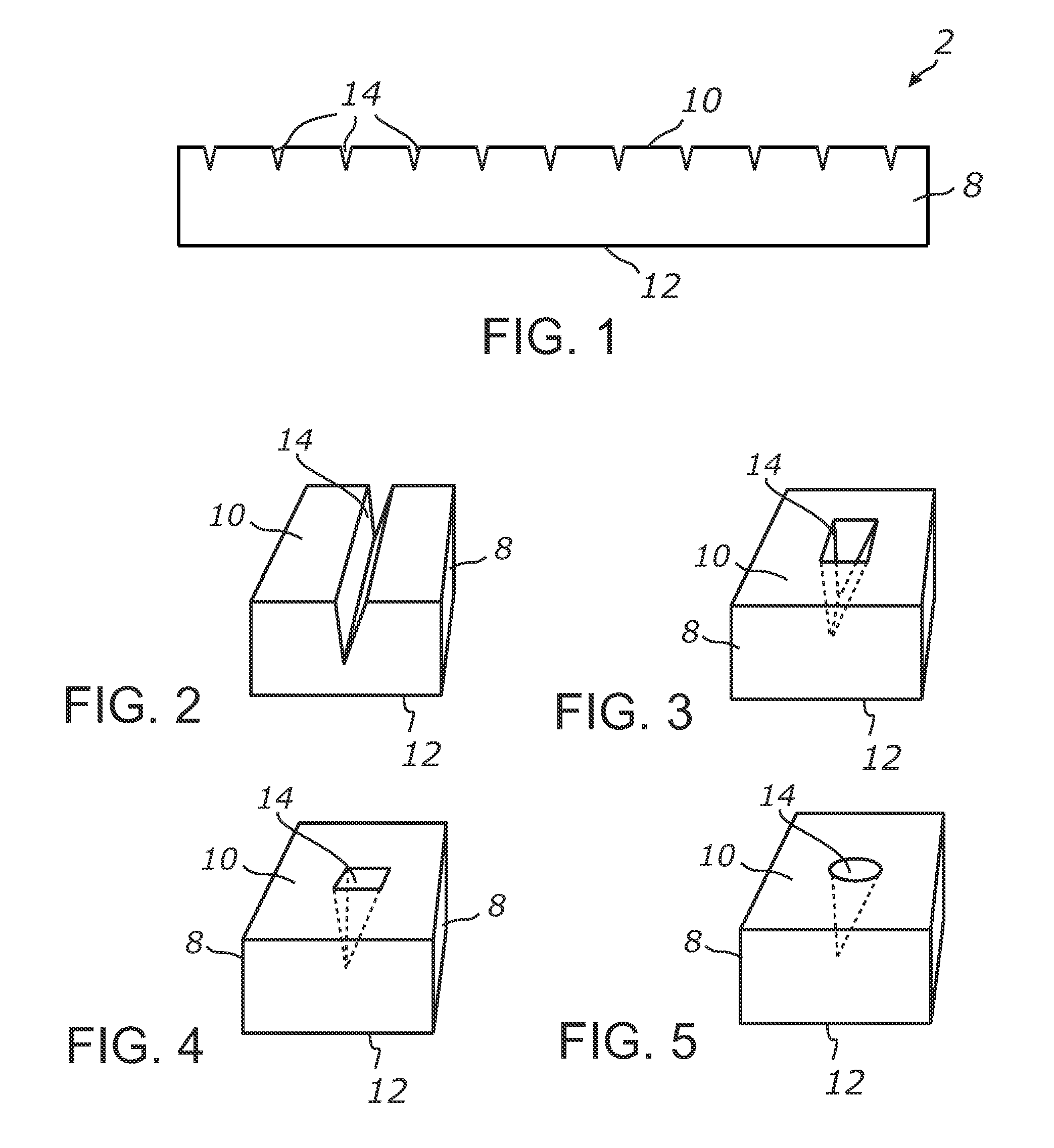
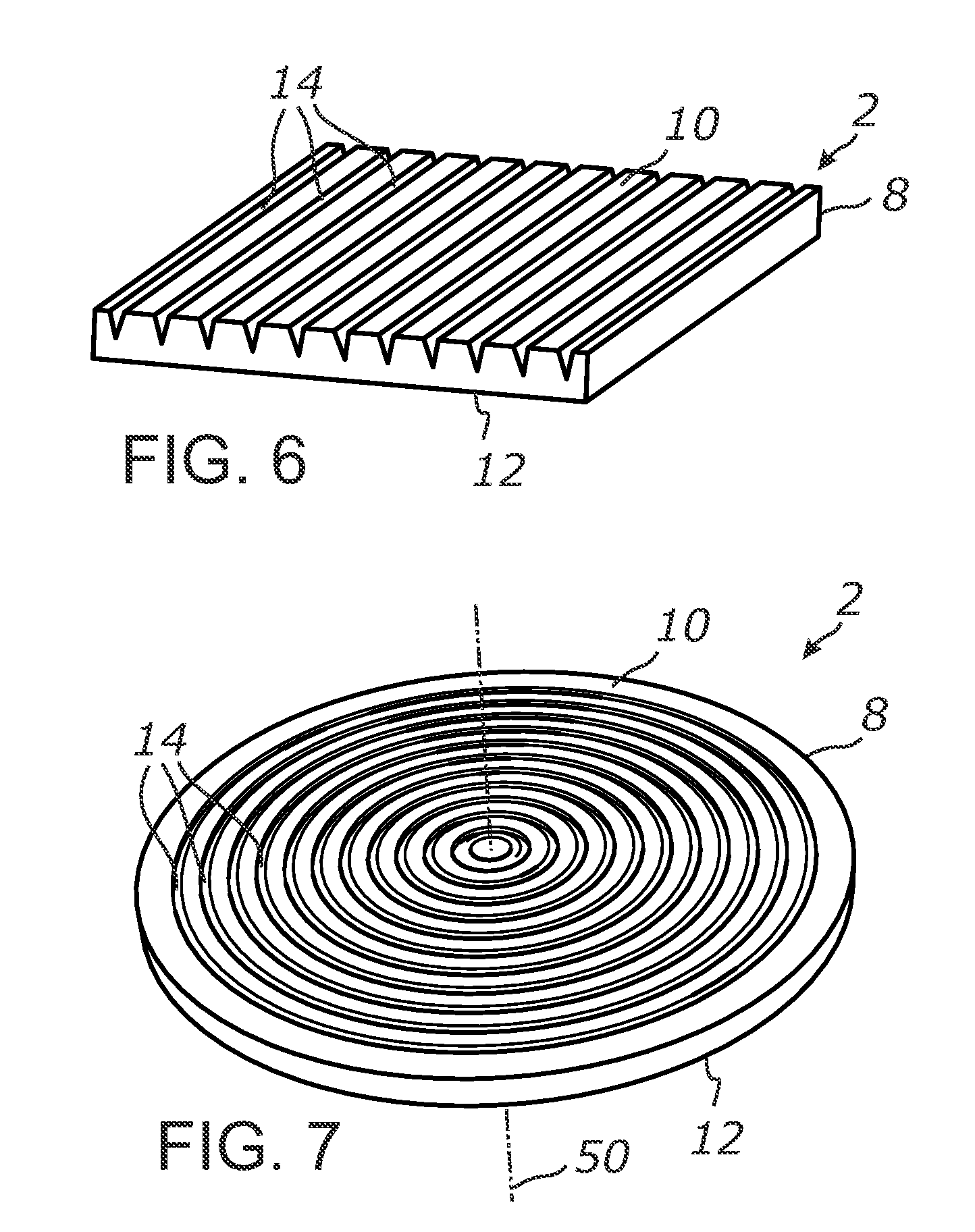
[0060]Referring more specifically to the drawings, for illustrative purposes the present invention is embodied in the apparatus generally shown in the preceding figures. It will be appreciated that the apparatus may vary as to configuration and as to details of the parts without departing from the basic concepts as disclosed herein. Furthermore, elements represented in one embodiment as taught herein are applicable without limitation to other embodiments taught herein, and in combination with those embodiments and what is known in the art.

[0061]A wide range of applications exist for the present invention in relation to the collection of electromagnetic radiant energy, such as light, in a broad spectrum or any suitable spectral bands or domains. Therefore, for the sake of simplicity of expression, without limiting generality of this invention, the term “light” will be used herein although the general terms “electromagnetic energy”, “electromagnetic radiation”, “radiant energy” or exe...


PUM


Abstract

A light trapping optical cover employing an optically transparent layer with a plurality of light deflecting elements. The transparent layer is configured for an unimpeded light passage through its body and has a broad light input surface and an opposing broad light output surface. The light deflecting elements deflect light incident into the transparent layer at a sufficiently high bend angle with respect to a surface normal and direct the deflected light toward a light harvesting device adjacent to the light output surface. The deflected light is retained by means of at least TIR in the system formed by the optical cover and the light harvesting device which allows for longer light propagation paths through the photoabsorptive layer of the device and for an improved light absorption. The optical cover may further employ a focusing array of light collectors being pairwise associated with the respective light deflecting elements.

Description

CROSS-REFERENCE TO RELATED APPLICATIONS[0001]This application is a continuation-in-part of application Ser. No. 12 / 764,867 filed Apr. 21, 2010. This application also claims priority from U.S. provisional application Ser. No. 61 / 461,522 filed on Jan. 18, 2011, incorporated herein by reference in its entirety.STATEMENT REGARDING FEDERALLY SPONSORED RESEARCH OR DEVELOPMENT[0002]Not ApplicableINCORPORATION-BY-REFERENCE OF MATERIAL SUBMITTED ON A COMPACT DISC[0003]Not ApplicableNOTICE OF MATERIAL SUBJECT TO COPYRIGHT PROTECTION[0004]A portion of the material in this patent document is subject to copyright protection under the copyright laws of the United States and of other countries. The owner of the copyright rights has no objection to the facsimile reproduction by anyone of the patent document or the patent disclosure, as it appears in the United States Patent and Trademark Office publicly available file or records, but otherwise reserves all copyright rights whatsoever. The copyright...

Claims


Application Information

Patent Timeline
IPC IPC(8): C12M3/00G02B5/10B01J19/12H01L31/0232
CPCG02B3/005G02B3/0056G02B19/0004Y02E10/52H02S40/00H02S40/22H01L31/0543G02B19/0028H01L31/054H01L31/0547H01L31/056
Inventor VASYLYEV, SERGIY VICTOROVICH
Owner S V V TECH INNOVATIONS
Why Eureka
Try Eureka