Optical path difference compensation mechanism for acquiring wave form signal of time-domain pulsed spectrometer

a technology of optical path difference and wave form signal, which is applied in the direction of optical radiation measurement, fluorescence/phosphorescence, instruments, etc., can solve the problems of requiring a long preparation time and a substantial burden on the operator, and achieve the effect of increasing the optical path length of the pulsed-light emitting unit and the aspherical mirror, increasing the spatial resolution of the sample to be measured, and increasing the optical path length

Active Publication Date: 2006-12-14
JAPAN SCI & TECH CORP +2
View PDF3 Cites 9 Cited by
  • Summary
  • Abstract
  • Description
  • Claims
  • Application Information

AI Technical Summary

Benefits of technology

[0061] The aspherical mirror disposed in the incident-side optical path between the pulsed-light emitting unit and the sample-unit entrance and exit optical systems converges the pulsed light towards the sample. On the other hand, the planar mirror is disposed between the pulsed-light emitting unit and the aspherical mirror and deflects the pulsed light emitted from the pulsed-light emitting unit. Therefore, the optical path length of the pulsed-light emitting unit and the aspherical mirror can be increased. By increasing this optical path length, it is possible to reduce, as much as possible, the focal area focused by the aspherical mirror, and consequently, it is possible to increase the spatial resolution of the sample to be measured.
[0062] Also, because the pulsed light is deflected at the planar mirror, it is possible, as well as increasing the optical path length, to make the apparatus configuration extremely compact.
[0063] Because the optical path length of the pulsed-light emitting unit and the aspherical mirror can be increased, it is possible make the distance between the aspherical mirror and the sample large, while maintaining a desired focal area. Therefore, sufficient space can be ensured around the sample, in other words, space for the sample-unit entrance and exit optical systems and the sample holder, thus allowing the degree of freedom for the analysis procedure to be increased.
[0064] In the same way as the incident-side optical path described above, the detection-side optical path between the detector and the sample-unit entrance and exit optical systems has a configuration in which a planar mirror is disposed between the aspherical mirror and the detector to increase the optical path length; therefore, it is possible to reduce, as much as possible, the focal area of the beam focused by the aspherical mirror, and consequently, it is possible to increase the spatial resolution of the sample to be measured.

Problems solved by technology

However, in order to carry out time-domain spectroscopy of such a wide range of samples and states thereof, different optical systems or optical arrangements are required accordingly, and therefore, there is a drawback in that a substantial burden is placed on the operator and, in addition, a long time is required for preparation and so on until measurement starts, after replacing the sample.

Method used


Image

  • Optical path difference compensation mechanism for acquiring wave form signal of time-domain pulsed spectrometer
  • Optical path difference compensation mechanism for acquiring wave form signal of time-domain pulsed spectrometer
  • Optical path difference compensation mechanism for acquiring wave form signal of time-domain pulsed spectrometer

Examples


Embodiment Construction

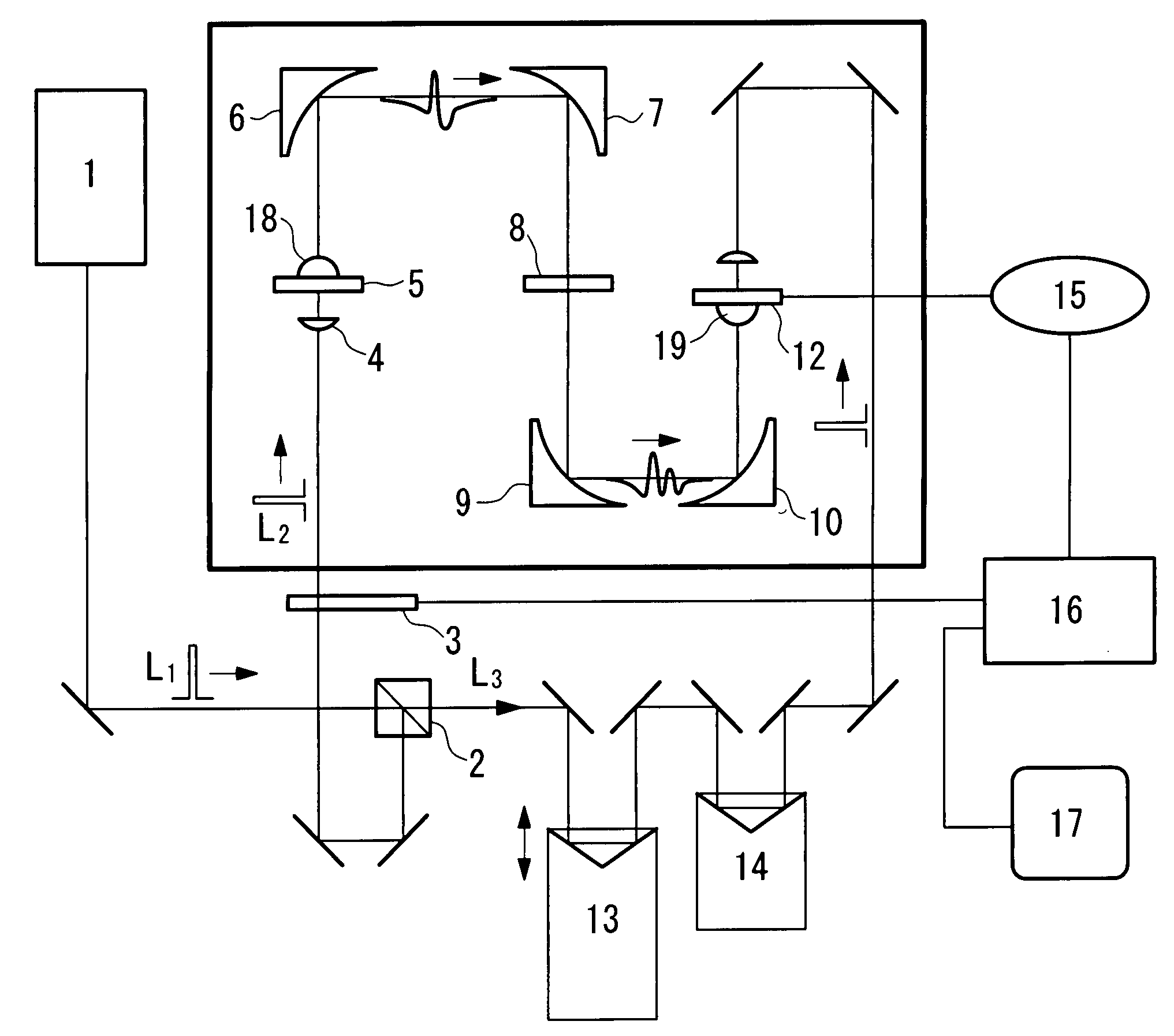
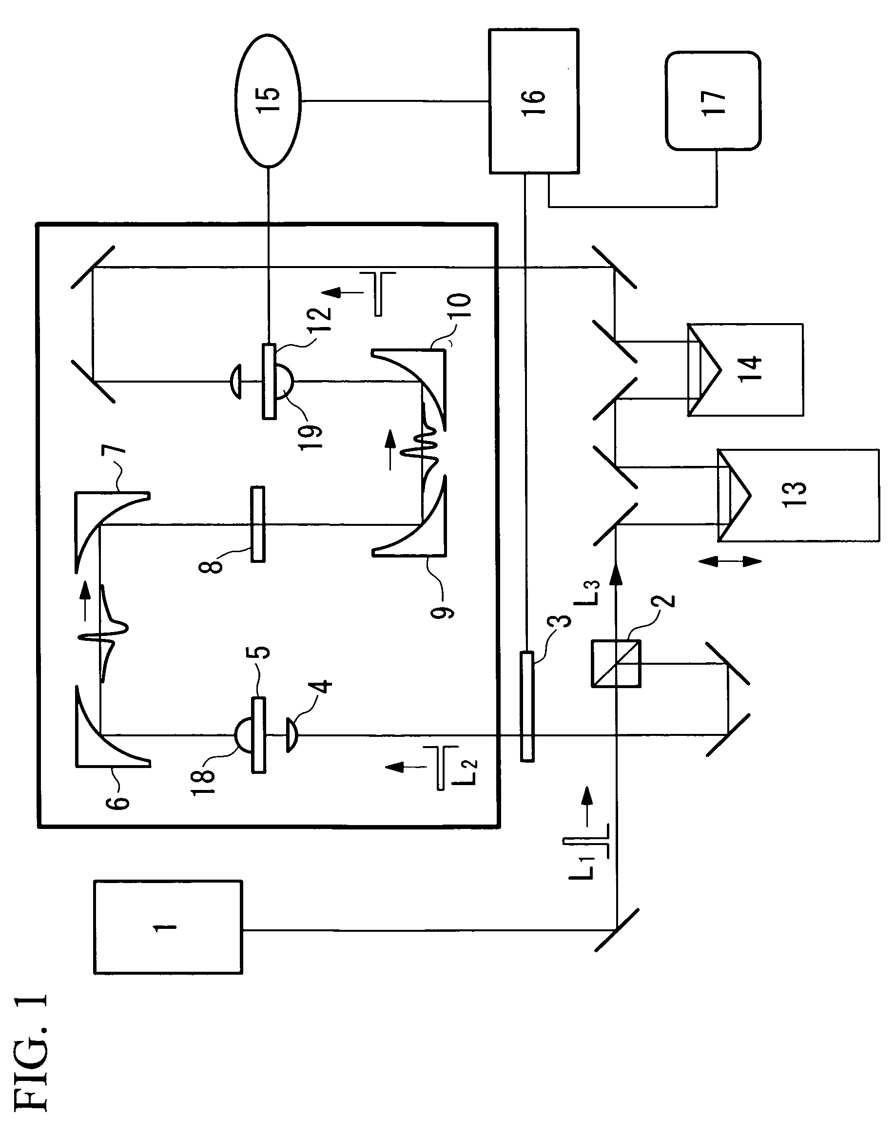
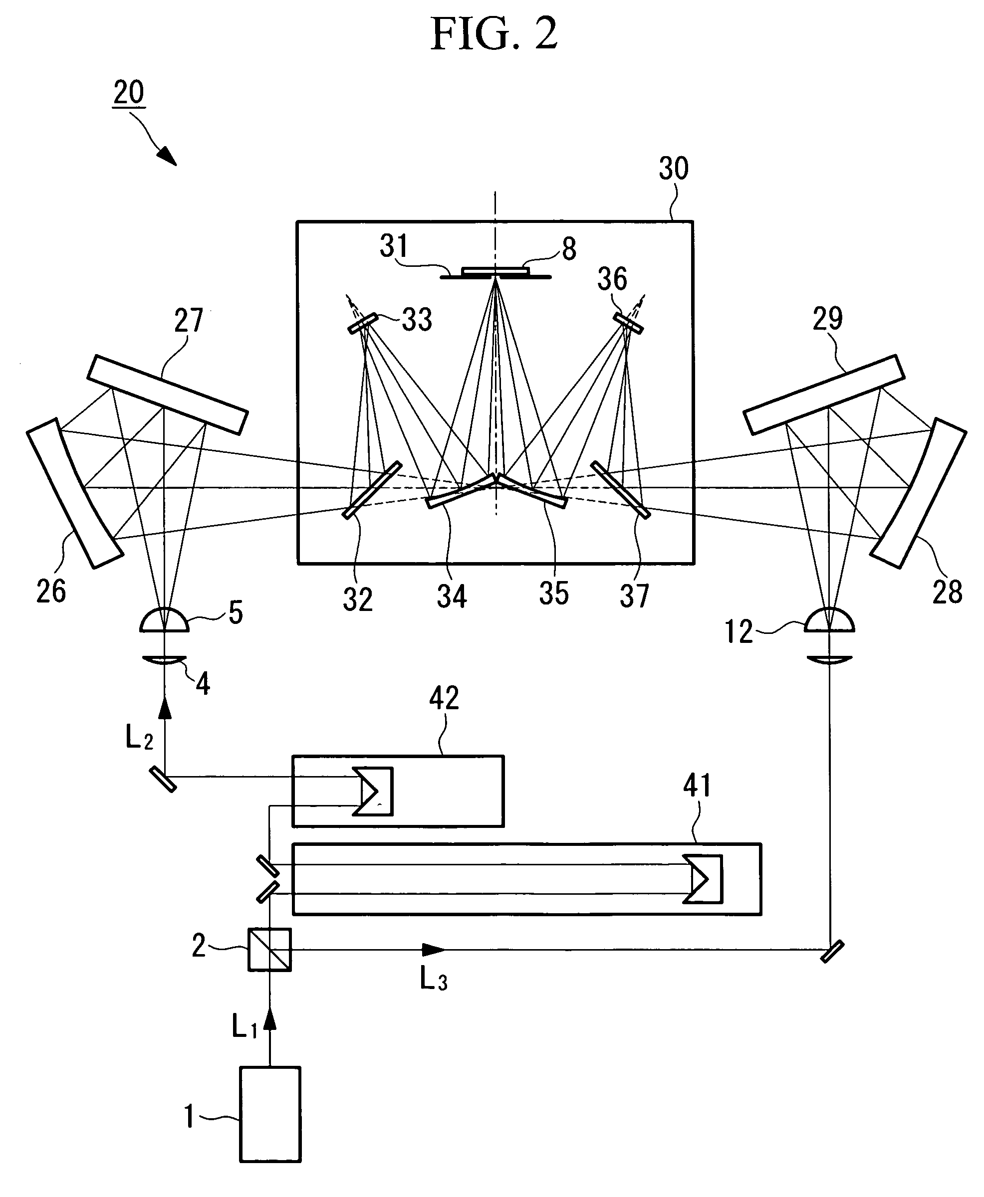
[0091]FIG. 2 shows the outline configuration of an embodiment of a time-domain pulsed spectroscopy apparatus and an optical-path-difference compensation device for wave form signal acquisition. The same constituent elements as those in FIG. 1 are assigned the same reference numerals and a description thereof is omitted.

[0092] This time-domain pulsed spectroscopy apparatus 20 includes a pulsed laser light source 1. Pulsed laser light L1 from this pulsed laser light source 1 is guided to a splitting unit 2 that splits it into excitation pulsed laser light L2 and detection pulsed laser light L3.

[0093] The time-domain pulsed spectroscopy apparatus 20 further includes a pulsed-light emitting unit 5 that emits pulsed light including wavelengths in the far-infrared wavelength region upon being irradiated with the excitation pulsed laser L2 and a detector 12 for detecting a wave form signal of the electric field intensity of reflected pulsed light from a sample 8, which is irradiated with...


PUM

PropertyMeasurementUnit
heightaaaaaaaaaa
depthaaaaaaaaaa
widthaaaaaaaaaa

Abstract

It is an object to provide a time-domain pulsed spectroscopy apparatus in which time-domain pulsed spectroscopy of multiple samples, states thereof, and so on can be carried out easily and in a short period of time. A time-domain pulsed spectroscopy apparatus of the present invention comprises a pulsed laser light source; a splitting unit configured to split pulsed laser light from the pulsed laser light source into excitation pulsed laser light and detection pulsed laser light; a pulsed-light emitting unit; a detector; a sample holder configured to hold the sample; and sample-unit entrance and exit optical systems configured to guide the pulsed light from the pulsed-light emitting unit to the sample and to guide to the detector pulsed light reflected from or transmitted through the sample due to the irradiation; wherein the time-domain pulsed spectroscopy apparatus further comprises: at least one optical-path-length varying unit for setting a photometric range, disposed in an incident-side optical path from the splitting unit to the pulsed-light emitting unit and/or in a detection-side optical path from the splitting unit to the detector; and at least one optical delay unit for the wave form signal measurement, disposed in the incident-side optical path from the splitting unit to the pulsed-light emitting unit and/or in the detection-side optical path from the splitting unit to the detector.

Description

TECHNICAL FIELD [0001] The present invention relates to a time-domain pulsed spectroscopy apparatus, and in particular, to a scanning mechanism and optical system alignment structure (optical arrangement) for acquiring a wave form signal thereof. BACKGROUND ART [0002] Due to the practical adoption of ultrashort pulsed laser technology in recent years, emission techniques and detection techniques for pulsed, coherent, far-infrared (particularly in the terahertz region) electromagnetic waves have progressed rapidly. Accordingly, time-domain pulsed spectroscopy using these pulsed far-infrared electromagnetic waves has become possible, and the pioneering development of practical time-domain pulsed spectroscopy apparatuses has progressed in Japan too. [0003] Time-domain pulsed spectroscopy is a spectroscopy method in which, by measuring the time-dependent electric field intensity of the pulsed electromagnetic field and by Fourier transforming this time-dependent data (time-series data), ...

Claims


Application Information

Patent Timeline
Patent Type & Authority Applications(United States)
IPC IPC(8): G01N21/35G01J3/08G01J3/42G01N21/3586G01N21/64
CPCG01J3/08G01N21/3586G01N2201/0698G01N2201/0696G01N21/3581G01J3/42
Inventor NISHIZAWA, SEIZIIWAMOTO, TOSHIYUKI
Owner JAPAN SCI & TECH CORP
Why Eureka
Try Eureka