Troffer-style optical assembly

a technology of optical assembly and troffer, which is applied in the direction of lighting and heating apparatus, semiconductor devices for light sources, light source combinations, etc., can solve the problems of very energy-inefficient light sources of incandescent lights, relatively inefficient leds, and leds can have a significantly longer operational li

Active Publication Date: 2012-06-07
IDEAL IND LIGHTING LLC
View PDF7 Cites 141 Cited by
  • Summary
  • Abstract
  • Description
  • Claims
  • Application Information

AI Technical Summary

Problems solved by technology

Incandescent lights are very energy-inefficient light sources with approximately ninety percent of the electricity they consume being released as heat rather than light.
Fluorescent light bulbs are more energy efficient than incandescent light bulbs by a factor of about 10, but are still relatively inefficient.
In addition, LEDs can have a significantly longer operational lifetime.
Incandescent light bulbs have relatively short lifetimes, with some having a lifetime in the range of about 750-1000 hours.
Fluorescent bulbs can also have lifetimes longer than incandescent bulbs such as in the range of approximately 10,000-20,000 hours, but provide less desirable color reproduction.
Because of the physical arrangement of the various source elements, multicolor sources often cast shadows with color separation and provide an output with poor color uniformity.
Thus, one challenge associated with multicolor light sources is good spatial color mixing over the entire range of viewing angles.
Uniformity typically improves with an increasing number of bounces, but each bounce has an associated optical loss.
Many of these devices are lossy and, thus, improve the color uniformity at the expense of the optical efficiency of the device.
One design challenge associated with multi-source luminaires is blending the light from LED sources within the luminaire so that the individual sources are not visible to an observer.
However, transmission through such heavily diffusive materials causes significant optical loss.
High power LEDs can draw large currents, generating significant amounts of heat that must be managed.
This can present challenges as plenum space decreases in modern structures.
Furthermore, the temperature in the plenum area is often several degrees warmer than the room environment below the ceiling, making it more difficult for the heat to escape into the plenum ambient.

Method used


Image

  • Troffer-style optical assembly
  • Troffer-style optical assembly
  • Troffer-style optical assembly

Examples


Embodiment Construction

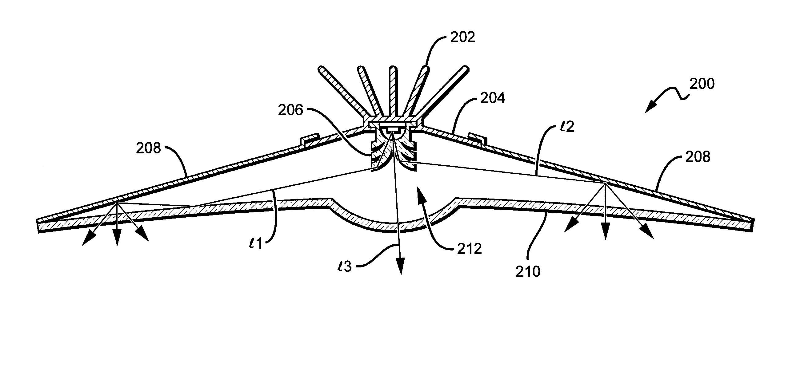
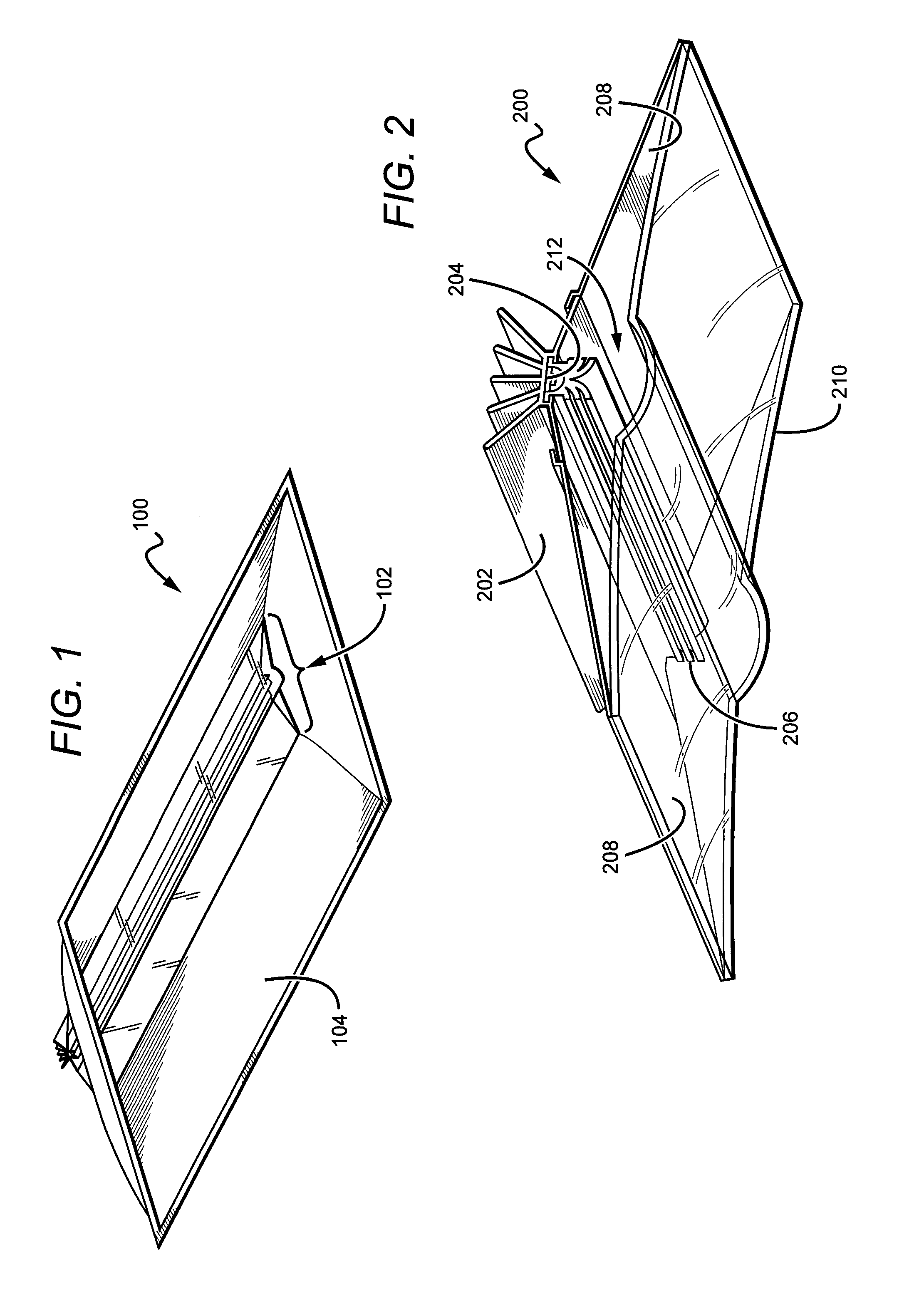
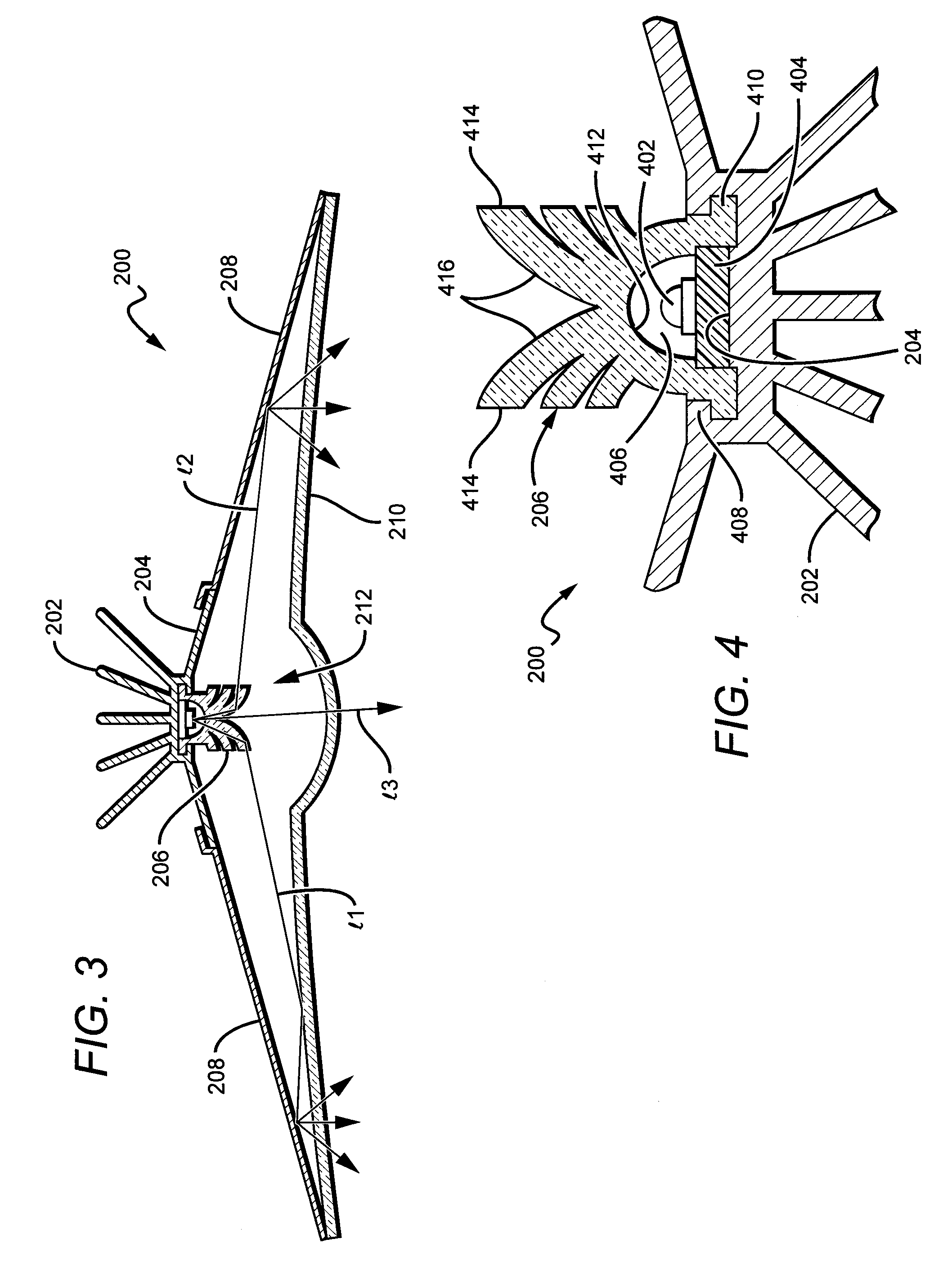
[0031]Embodiments of the present invention provide a troffer-style fixture that is particularly well-suited for use with solid state light sources, such as LEDs. The troffer comprises a light engine unit that is surrounded on its perimeter by a reflective pan. An elongated heat sink comprises a mount surface for light sources. An elongated lens is mounted on or above the heat sink such that an interior space is defined between the two elements. The space is designed to accommodate the light emitters which may come on prefabricated a light strip, for example. One or more reflectors extend out away from the heat sink on the mount surface side. A lens plate is mounted to proximate to the heat sink and extends out to the edge of the reflector(s). An interior cavity is at least partially defined by the reflector(s), the lens plates, and the heat sink. A portion of the heat sink is exposed to the ambient environment outside of the cavity. The portion of the heat sink inside the cavity fun...


PUM


Abstract

A troffer-style fixture. The fixture is particularly well-suited for use with solid state light sources. The troffer comprises a light engine unit surrounded by a reflective pan. An elongated heat sink comprises a mount surface for light sources. An elongated lens is mounted on or above the heat sink. The mount surface is designed to accommodate the light emitters which may come on prefabricated a light strip. One or more reflectors extend out away from the heat sink on the mount surface side. A lens plate is mounted to proximate to the heat sink and extends out to the edge of the reflector(s). An interior cavity is at least partially defined by the reflector(s), the lens plates, and the heat sink. One or more light sources disposed along the heat sink mount surface emit light into the interior cavity where it can be mixed and/or shaped before it is emitted.

Description

BACKGROUND OF THE INVENTION[0001]1. Field of the Invention[0002]The invention relates to troffer-style lighting fixtures and, more particularly, to troffer-style fixtures that are well-suited for use with solid state lighting sources, such as light emitting diodes (LEDs).[0003]2. Description of the Related Art[0004]Troffer-style fixtures are ubiquitous in commercial office and industrial spaces throughout the world. In many instances these troffers house elongated fluorescent light bulbs that span the length of the troffer. Troffers may be mounted to or suspended from ceilings. Often the troffer may be recessed into the ceiling, with the back side of the troffer protruding into the plenum area above the ceiling. Typically, elements of the troffer on the back side dissipate heat generated by the light source into the plenum where air can be circulated to facilitate the cooling mechanism. U.S. Pat. No. 5,823,663 to Bell, et al. and U.S. Pat. No. 6,210,025 to Schmidt, et al. are exampl...

Claims


Application Information

Patent Timeline
Patent Type & Authority Applications(United States)
IPC IPC(8): F21V29/00F21S4/00F21V5/00F21V7/00F21V9/00
CPCF21K9/52F21S4/003F21V15/013F21Y2101/02F21Y2105/001F21V5/04F21V29/777F21V7/0091F21Y2113/005F21V29/505F21V29/745F21V29/75F21V7/005F21S4/20F21Y2105/10F21K9/61F21Y2115/10F21Y2113/13F21Y2115/30F21V5/045F21V29/70
Inventor PICKARD, PAUL KENNETH
Owner IDEAL IND LIGHTING LLC
Why Eureka
Try Eureka