Transtibial socket for external prosthesis

a technology of external prosthesis and transtibial socket, which is applied in the field of lower limb external prosthesis, can solve the problems of lack of rotational control, reduced range of motion, etc., and achieve the effects of reducing pressure on the patellar tendon, reducing curvature and/or shape, and eliminating or de-emphasizing the patellar bar

Inactive Publication Date: 2012-06-07
COYOTE DESIGN & MFG INC
View PDF2 Cites 0 Cited by
  • Summary
  • Abstract
  • Description
  • Claims
  • Application Information

AI Technical Summary

Benefits of technology

[0009]The invention comprises a socket with a modified curvature and / or shape, which eliminates or de-emphasizes the patellar bar to eliminate or reduce pressure on the patellar tendon, and, instead, enhances support of the anterior tibial condyle and / or tibial tubercle. The preferred curvature and / or shape comprises a lowered socket edge in the region of the user's patellar tendon, so that the hard structure of the socket does not directly support or impinge upon the patellar tendon. The invented socket may include indentations on each side of the lowered edge, thus, on each side of and substantially out of the way of the patellar tendon, for helping to “capture” a portion of the tibia for improved rotational control. This combination of shapes and curvatures provides for improved rotational control, comfort, and range of motion.
[0010]In the preferred embodiment, the conventional patellar bar is eliminated, and the upper edge of the hard wall of the socket is preferably lowered relative to where it would be if the hard wall were intended to contact / support the patellar tendon region of the residual limb. A strap, patch, cloth, or other member may be placed at the “trough” or “notch” of the lowered, typically downwardly-curving edge of the socket. Preferably, this member is somewhat flexible, somewhat elastic, and / or otherwise forgiving, while also giving some degree of containment of the portion of the liner-covered residual limb that contacts said member. A very flexible and / or cushioning member (such as a rubber or fabric sheet) may be placed in this position for less aggressive walkers, or a somewhat flexible but more rigid and inelastic member (such as leather) may be placed in this position for a more aggressive walker. Or, the member may be entirely eliminated, depending on the comfort, control, and containment needs of the user, so that there is no socket portion or other structure supporting or contacting the liner-covered residual limb in the area of the patellar tendon. Thus, this region of the socket may be customized to the walker, while giving increased range of motion compared to conventional sockets for transtibial / Symes amputees.

Problems solved by technology

While the bar's support of, and impingement against, the patellar tendon in prior art sockets is intended to provide non-bone contact point and support, the inventor believes that this type of support actually leads to discomfort, lack of rotational control, and reduced range of motion.

Method used


Image

  • Transtibial socket for external prosthesis
  • Transtibial socket for external prosthesis
  • Transtibial socket for external prosthesis

Examples


Embodiment Construction

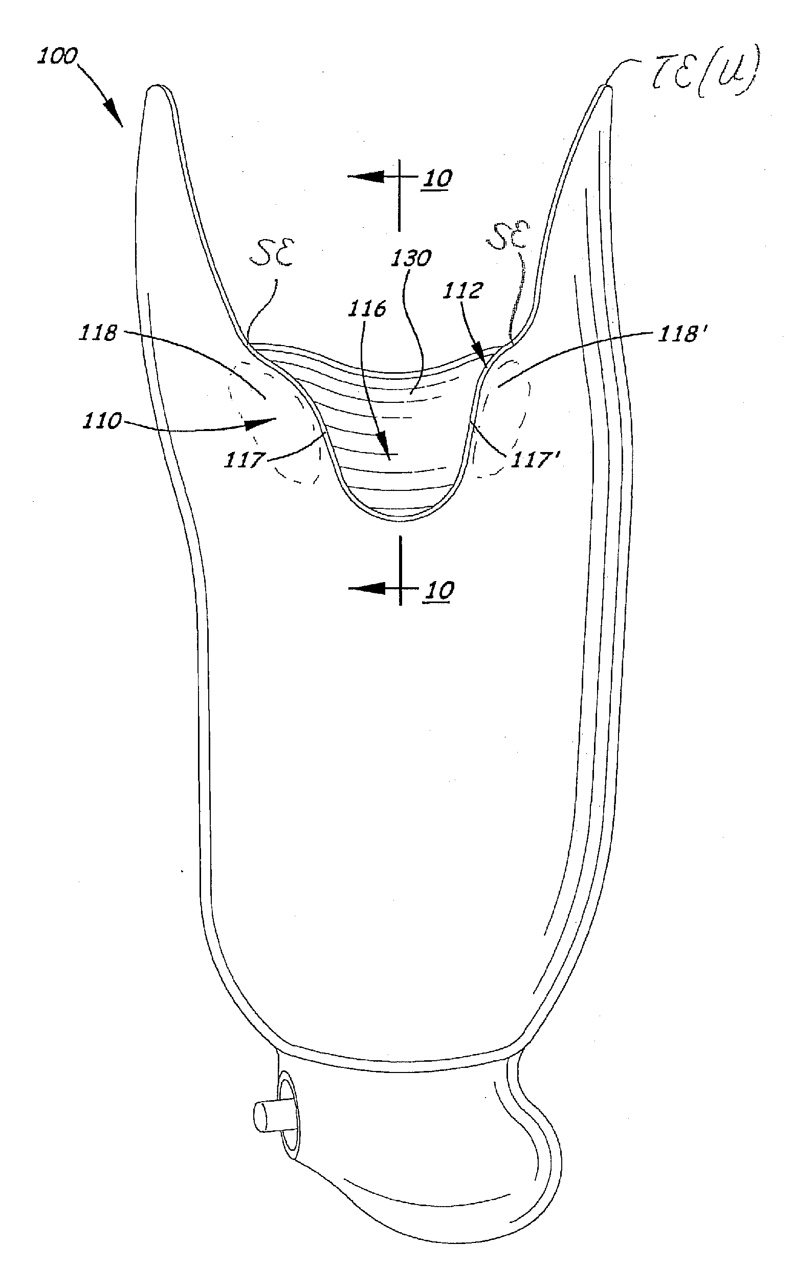
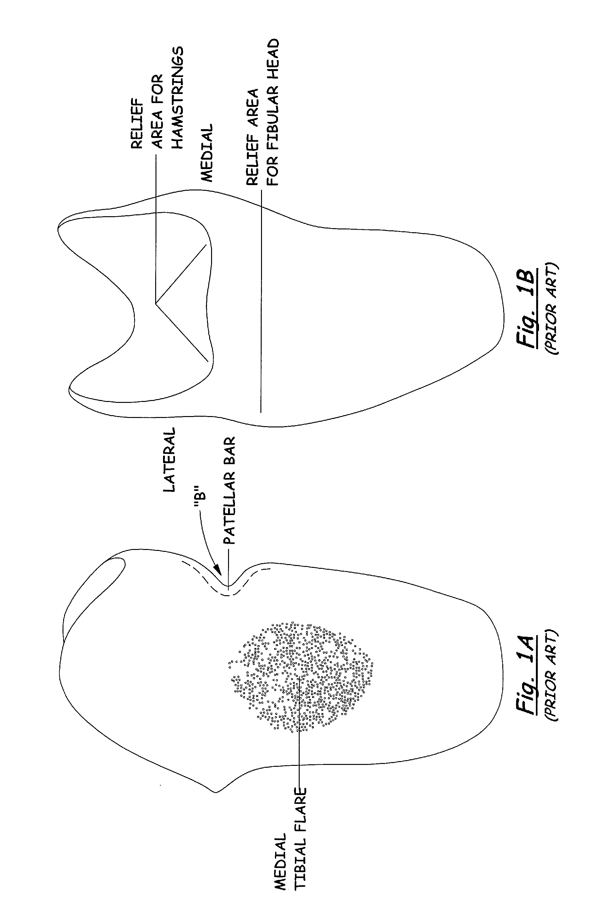
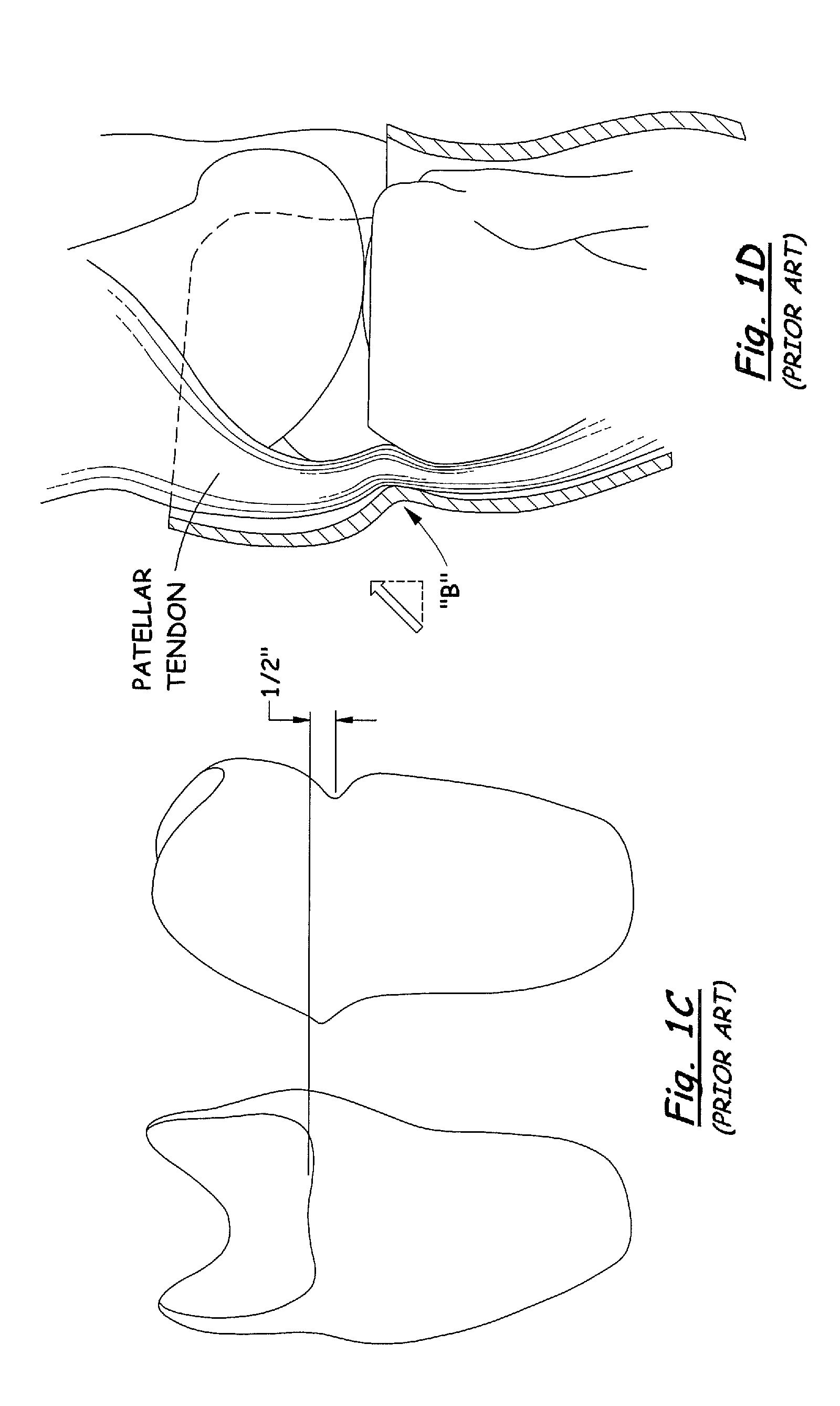
[0024]Referring to FIGS. 1A-D, and 2-5, one may see examples of prior art sockets with embodiments of tendon-support hard socket wall ledges or inward-curvature, called “patellar bars” as discussed above. Referring to FIGS. 2-5, socket 10 has a top edge 12 and, near the top edge, is the concave (from the outside) bar B. As discussed above, the bar B need not always be so close to the top edge 12, as illustrated in FIGS. 1A-D. Also, there may be ways of making a prior art patellar bar, other than curvature of the socket wall, for example, placement or molding of additional material at the inner wall of the socket to provide said “ledge” against which the patellar tendon rests / pushes.

[0025]The bar B provides a substantially-horizontal “shelf”15 on the inside of the socket against which the patellar tendon is placed. One may see, especially in FIGS. 2 and 3, that the top edge in the region of the prior art bar B (that is near the top edge TE) is typically a gentle, large-radiused edge,...


PUM


Abstract

A prosthetic hard socket has a modified curvature and / or shape that improves rotational control, comfort, and range of motion including even full extension or hyperextension. The hard socket eliminates or de-emphasizes the patellar bar, to eliminate or reduce pressure on the wearer's patellar tendon, and enhances support of the anterior tibial condyle and / or tibial tubercle. Thus, the patellar tendon preferably is not weight-bearing. A lowered socket edge and / or a gap in the socket wall in the region of the patellar tendon prevents the hard structure of the socket from directly supporting or pressing upon the patellar tendon. Inwardly-protruding regions on each side of the lowered edge / gap help “capture” or otherwise press on a portion of the tibia. A flexible and / or cushioning member may be placed in the gap / trough.

Description

[0001]This application is a continuation of Non-Provisional Patent Application Ser. No. 11 / 949,018, filed Nov. 30, 2007 and issuing as Pat. No. 8,075,632 on Dec. 13, 2011, which claims priority of Provisional Application 60 / 872,287, filed Nov. 30, 2006, the entire disclosure of which Provisional Application is incorporated herein by this reference.BACKGROUND OF THE INVENTION[0002]1. Field of the Invention[0003]This invention relates to the field of lower limb external prosthetics, specifically below-the-knee amputations, such as transtibial and Symes amputations. The invention relates to prosthetics sockets that provide enhanced comfort and control without providing a patellar tendon bar.[0004]2. Related Art[0005]Conventional hard sockets for lower limb external prosthetics, for example, those portrayed in FIGS. 1-5, comprise a patellar-tendon-bar. It should be noted that the patellar-tendon bar (B) may be located at various levels (vertical distances along the socket), depending up...

Claims


Application Information

Patent Timeline
Patent Type & Authority Applications(United States)
IPC IPC(8): A61F2/78B23P17/04
CPCA61F2/7812A61F2/80Y10T29/49A61F2002/607A61F2220/005A61F2002/30448
Inventor PERKINS, DALE
Owner COYOTE DESIGN & MFG INC
Why Eureka
Try Eureka