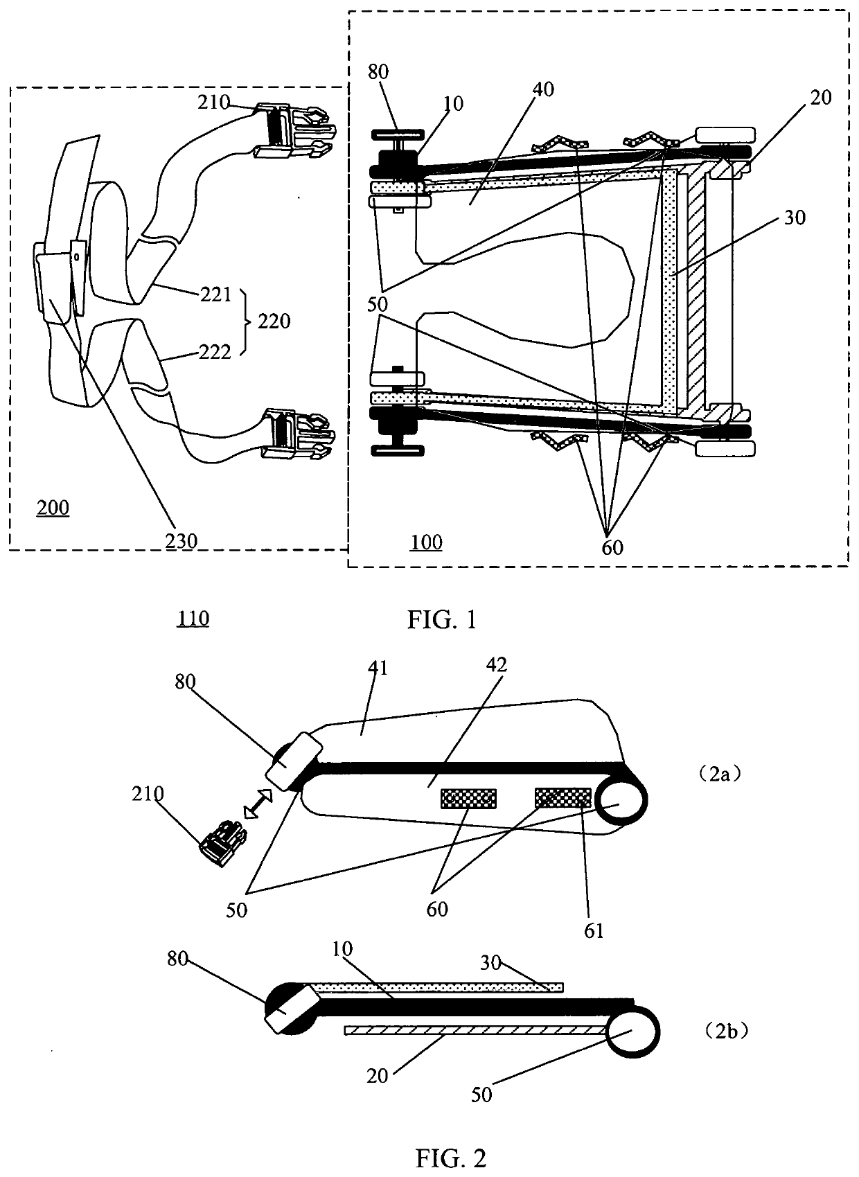
Travel pillow

Active Publication Date: 2020-10-29
ZHU BRIAN Y +1
View PDF0 Cites 1 Cited by
  • Summary
  • Abstract
  • Description
  • Claims
  • Application Information

AI Technical Summary

Benefits of technology

The present invention provides a travel pillow that can be adjusted to different angles and heights for comfortable rest and reduced pressure on the neck. The pillow includes locking members to secure it to a table or human body, and a fastening means to secure it to a trolley case. The pillow is stable and secure even when under pressure. It also has improved portability. Overall, the travel pillow enhances travel experiences and increases usages while reducing discomfort.

Problems solved by technology

It may take a long time to travel by vehicles, airplanes, etc., and a traveler needs to maintain a secured posture or an uncomfortable posture for a long time, or has to rest or sleep in a place where there is no a bed.
Therefore, the traveler may have the problems of muscle stiffness or exhaustion, especially neck soreness.
However, there are still many problems in this travel pillow: 1) when a traveler want to lean forward on the front table on the plane, it may be difficult or uncomfortable to bend down because a distance between front and rear seats are not enough or the table position is too low; 2) when a belt is used to secure the travel pillow on a seat back, the head of a traveler can move freely left or right and is not fixed at desirable position while the traveler leans forward between the travel pillow and the seat back and rests against the travel pillow; 3) when a belt is used to secure the travel pillow on human chest of a traveler, the belt surrounding the back of the traveler's neck can put a lot of unwanted pressure on the traveler's neck.

Method used


Image

  • Travel pillow
  • Travel pillow
  • Travel pillow

Examples


first embodiment

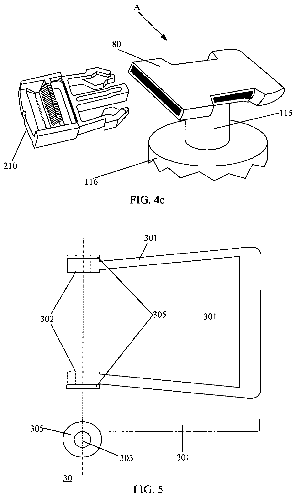
[0076]FIG. 7a shows a structural diagram of the non-slip member according to the present disclosure, and FIG. 7b shows an application diagram of the anti-slip member.

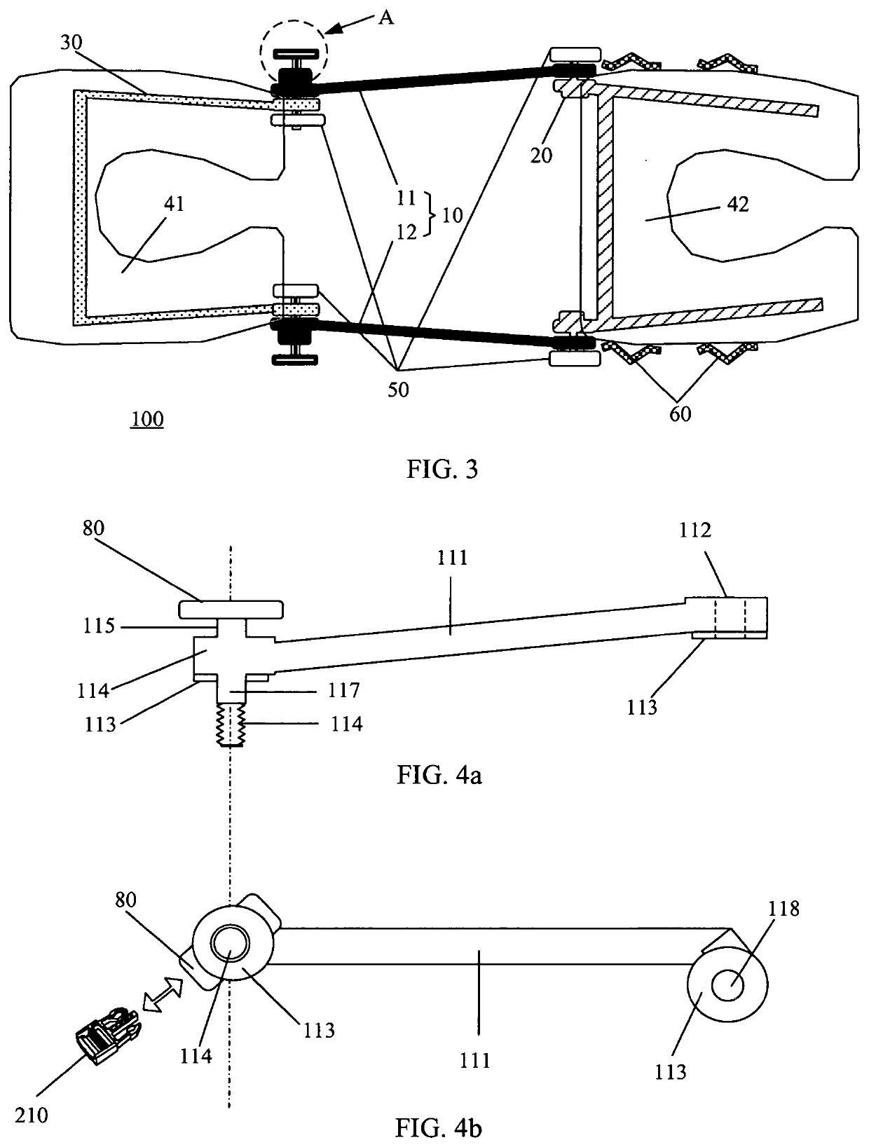
[0077]Taking the rough surface 113 of the connecting rod 10 as an example, referring to FIG. 7a, the rough surface 113 is saw-toothed, and the shape of each of a protruding teeth and each of a recessed tooth is at least partially engageable. Referring to FIG. 7b, taking the first end of the connecting rod 10 and the frame 30 as an example, the external thread 114 and the screw 117 of the connecting rod 10 sequentially pass through the shaft hole 303 of the frame 30, rotating the frame 30, adjusting the relative angle between the connecting rod 10 and the frame 30, and the connecting rod 10 and the frame 30 are brought close again, so that the anti-slip members 113 and 305 are in contact with each other. Slightly adjusting the relative angle between the connecting rod 10 and the frame 30, so that the protruding teeth of ...

second embodiment

[0079]Referring to FIGS. 8 and 9, a frame 20 of the second embodiment comprises a U-shaped frame 201, ends 202 respectively connected to both sides of the bottom of the U-shaped frame 201, a fourth cylinder 204 on the same straight line as the center of the end 202, and a fifth cylinder 205 having a threaded side, on the sides of the end 202 close to the connecting rod 10, there is also an end of a connecting rod of a travel pillow 203. The diameters of the fourth cylinder 204 and the fifth cylinder 205 are slightly smaller than the diameter of the shaft hole 118 of the end 112 of the connecting rod 10, and therefore, the shaft hole 118 is capable of passing through the fourth cylinder 204 and the fifth cylinder 205, so that the frame 20 is movably coupled to the connecting rod 10. The non-slip member 203 of the second pillow body 42 is used in conjunction with the rough surface 113 of the connecting rod 10 to maintain the second pillow body 42 and the connecting rod 10 at a set ang...

fourth embodiment

[0083]Referring to FIGS. 13 to 15, the travel pillow frame of the fourth embodiment comprises a frame 30 of the first pillow body 41, a frame 20 of the second pillow body 42, a connecting rod 10 for connecting the first pillow body 41 and the second pillow body 42, and a locking member 70 for locking the structure at the connection end.

[0084]The ends of the connecting rods 10 respectively have shaft holes 118 and non-slip members 113. The end of the frame 20 and the frame 30 is a bifurcated structure, and the inside of the bifurcated structure has an end of a connecting rod of a travel pillow and a shaft hole, and the end of the connecting rod 10 can be fitted into the bifurcated end of the frame 20 and the frame 30. On the side surface of the end of the frame 30, a buckle socket 80 is also connected for connection with the fastening means 200.

[0085]Taking the end of the frame 30 and the connecting rod 10 as an example, referring to FIG. 16 and FIG. 17, at the bifurcated connection ...


PUM


Abstract

The present disclosure relates to a travel pillow. The travel pillow comprises a connecting rod having a first end and a second end, and a first pillow body and a second pillow body. Each of the first pillow body and the second pillow body comprises a frame and a soft cushion mounted on the frame. One end of the frame of the first pillow body is coupled to the first end of the connecting rod. The first pillow body is configured to be rotated at the first end of the connecting rods and locked at a predetermined angle. One end of the frame of the second pillow body is coupled to the second end of the connecting rod. The second pillow body is configured to be rotated at the second end of the connecting rods and locked at a predetermined angle. The travel pillow has a height which is adjusted by changing the angle between the first pillow body and the connecting rod and the angle between the second pillow body and the connecting rod. Moreover, a fastening means is used for carrying and securing the travel pillow.

Description

TECHNICAL FIELD[0001]The present disclosure relates to the field of travel goods, and more particularly to a travel pillow.BACKGROUND[0002]With the improvement of people's living standards, travel has become an important means for people to improve their quality of life. It may take a long time to travel by vehicles, airplanes, etc., and a traveler needs to maintain a secured posture or an uncomfortable posture for a long time, or has to rest or sleep in a place where there is no a bed. Therefore, the traveler may have the problems of muscle stiffness or exhaustion, especially neck soreness.[0003]In order to relieve neck soreness, the traveler usually choose to carry a travel pillow so that the traveler can rest or sleep comfortably when sitting in an upright or forward position. One kind of travel pillows, according to conventional technology, comprises two pillow bodies that are connected by a joint and may be rotated at the joint. The traveler can adjust the relative positions of...

Claims


Application Information

Patent Timeline
IPC IPC(8): A47C16/00A47G9/10F16M13/04
CPCA47G9/1027A47G2009/1018A47G9/1081A47G9/1009F16M13/04A47C16/00A47C7/383F16M11/2021F16M11/10F16M2200/024
Inventor ZHU, BRIAN Y.ZHU, HUILONG
Owner ZHU BRIAN Y
Why Eureka
Try Eureka