For the reasons cited above, it is an object of the present invention to provide a nail trimmer that provides sufficient force to easily
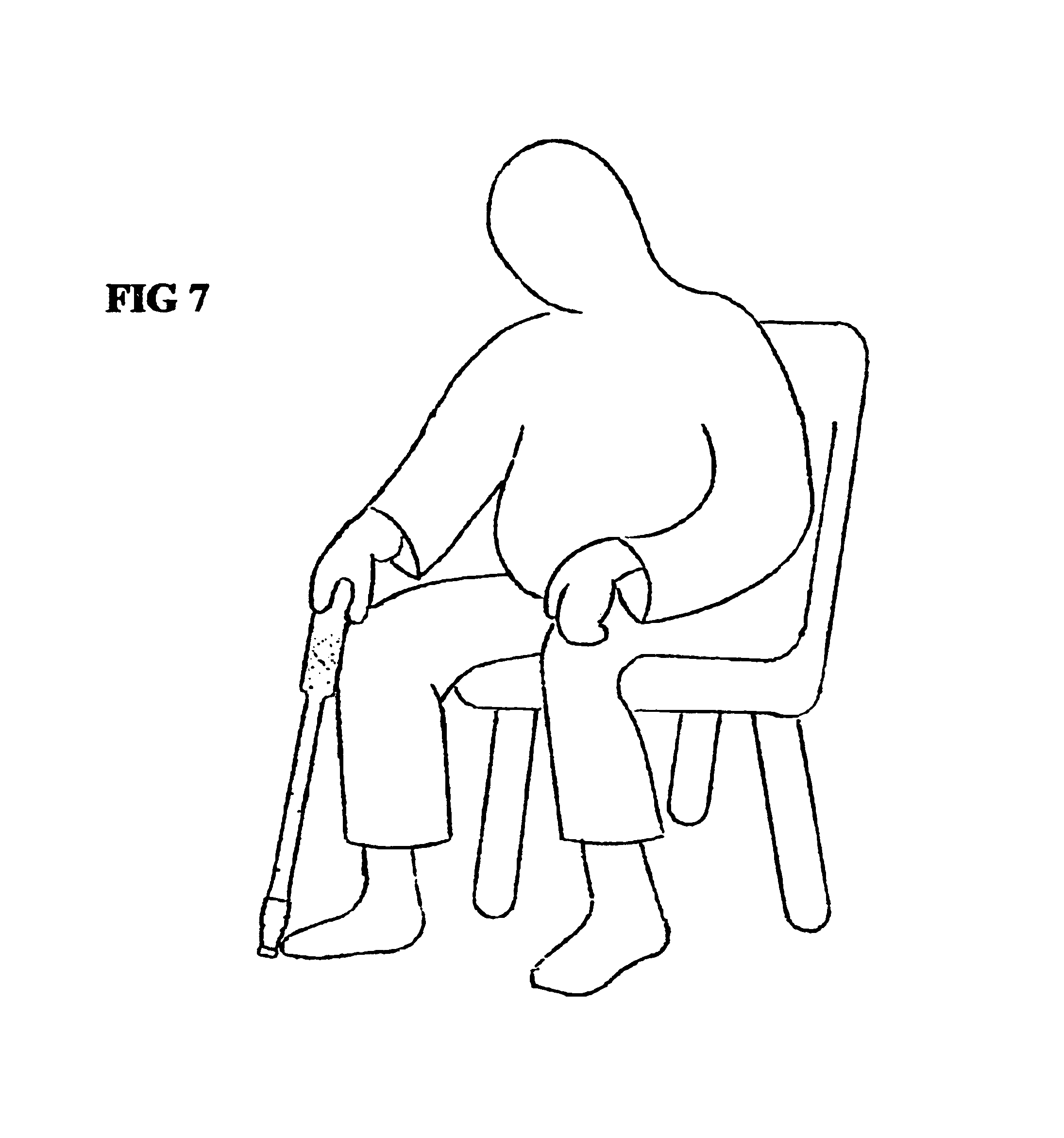
cut through keratin material of a toenail. It is a further object to provide such a nail trimmer that allows the user to maintain a comfortable posture when cutting toenails. It is a yet further object to provide such a nail trimmer that is safe and easy to use, even for a
sight-handicapped person.
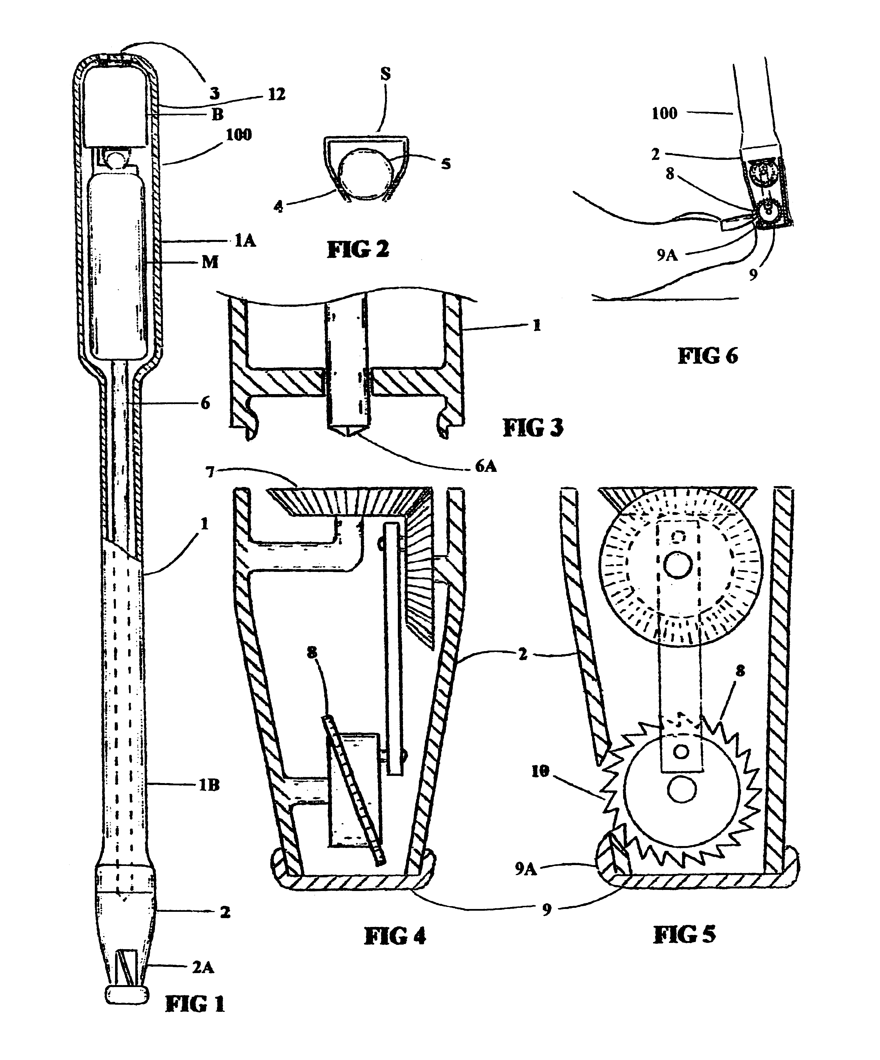
Ideally, the cutting blade is a dado blade that removes a wide swath of keratin material relative to the width of the cutting blade. Although other types of cutting blades may be used in the nail trimmer according to the invention, the use of a dado blade is preferred over other types because the dado action provides a smooth trimming action and finished nail surface. A saw-toothed blade is preferred, as it provides a
rapid rate of
material removal, but a similarly sized and shaped
carbide cutting / shaping wheel is also suitable for this application. Oscillating and rotating blades are described in some of the prior art, but none provide the ease and smoothness of use provided by a dado blade, famous in cabinet making for smooth and precise cutting unmatched by any other blade.
As a safety means, the ON / OFF switch that controls the motor may be a gravity operated switch that switches the motor on only when the nail trimmer is held in a proper orientation, or a switch that requires that the user keep it depressed for continued operation, in other words, the switch switches automatically to the OFF position when the user lets go of it. Such safety switches provide assurance that the unit is operated only with intent and in the prescribed orientation for its intended function. Use of a gravity operated ON / OFF switch has the additional
advantage in that it permits those with arthritic or other physical
weakness in the hands to comfortably hold and easily use the nail trimmer, without having to apply pressure to the ON / OFF switch.
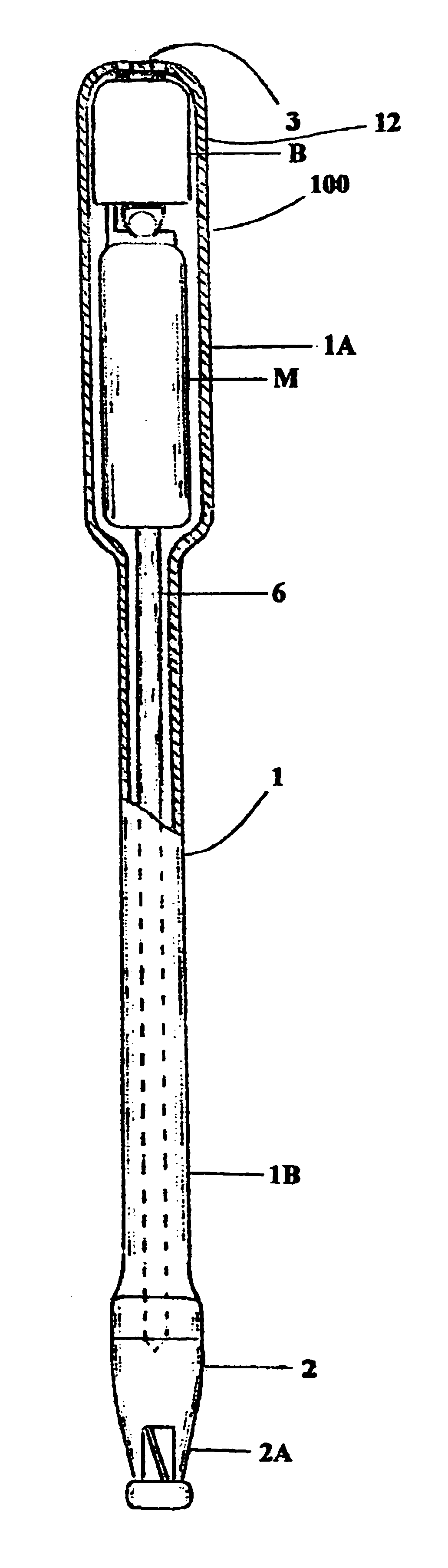
The exterior of the extension housing, especially that part that encloses the motor and serves as the
handle, is ideally provided with a material or treatment that is pleasant to the touch, and facilitates a secure sense of gripping. The extension housing completely encloses the power and drive means for the cutting blade. The blade in the trimmer unit is almost completely enclosed by the trimmer
unit housing. A small opening is provided in the trimmer
unit housing to enable access to the cutting blade. The
waste material is collected in the bottom of the trimmer unit, in a space provided beneath the cutting blade. A removable cap is fitted across the bottom of the trimmer unit. The cap serves a
dual purpose. For one, it is easily removable from the trimmer unit, to allow disposal of the
waste material collected within. The inside of the trimmer unit can be thoroughly washed out. For another, the cap serves as a guide and support for the
toe with the toenail to be trimmed. To use the nail trimmer, the end of the trimmer unit with the cap is placed upon a floor or other surface, for example. The trimmer unit is moved into a cutting position by moving it up so close to the nail to be trimmed that the
front edge of the cap, that is, the edge of the cap just below the blade opening, is positioned at the tip of the
toe, just under the toenail. The cap has a contour that provides some support for the toe during the trimming operation and provides an important
tactile sensation that allows a
sight-impaired person to properly position the nail trimmer for use by feel alone. The cap also prevents injury in that it positions the toe properly in front of the blade, yet prevents the toe from moving in so close to the exposed cutting blade that it can be cut.
The nail trimmer according to the invention provides a lightweight, maneuverable, and convenient tool for comfortable, even pleasurable trimming of finger and toenails, for the obese, the physically challenged, the elderly, and the
sight-handicapped persons.

