Portable handheld work apparatus

a handheld work and work technology, applied in the field of portable handheld work devices, can solve problems such as unfavorable work positions, and achieve the effect of preventing the lying of work tools

Inactive Publication Date: 2005-06-14
ANDREAS STIHL AG & CO KG
View PDF8 Cites 27 Cited by
  • Summary
  • Abstract
  • Description
  • Claims
  • Application Information

AI Technical Summary

Benefits of technology

[0003]It is an object of the invention to provide a work apparatus of the kind described above which can be handled comfortably.
[0005]In the work position of the motorized apparatus, at least one handle is directed upwardly and away from the surface of the ground. For this reason, a favorable work position results for the operator and makes it possible for the operator to work with the work apparatus without fatigue.
[0006]A comfortable position of the hands by the operator is achieved when two handles are provided which run upwardly toward each other when the motorized apparatus is in the work position and are inclined in the direction toward the work tool when in this work position. It is especially provided that two handles are arranged on two symmetrically-configured handle tubes. It is practical when the handle tubes enclose an intermediate space open toward the operator. In this way, the operator can step between the handle tubes and the handles come to rest laterally of the body of the operator. This facilitates guiding the work apparatus.
[0007]The handle tubes can be folded over toward the frame and are fixed thereon to make possible a simple transport of the work apparatus. Advantageously, the handle tubes are arranged on both sides of the frame in the folded condition. With the folded-over handle tubes, the work apparatus forms a compact package which can be easily transported. At the same time, only a small storage space is needed for the work apparatus when the handle tubes are folded over. For the transport of the work apparatus, it is provided that a rearward carrying handle is arranged on the end of the frame facing toward the handles. It is advantageous to also have a forward carrying handle in a region between the drive motor and the work tool. To make possible a simple transport of the work apparatus, the forward carrying handle acts approximately at the center of gravity of the work apparatus when the handle tubes are folded over. In this way, the work apparatus can be lifted with one hand without the work apparatus tilting so that a danger of injury to the operator is precluded.
[0008]Advantageously, the rearward handle has lateral supports in which the handle tubes lie in the folded condition. Because of the support of the handle tubes, it is ensured that the handles do not come in contact with the ground when the work apparatus is set down and damage or a dirtying of the handles is avoided.
[0011]The frame has a forward support and a rearward support whose connecting line runs at a spacing to the work tool. With this, a good placement of the work apparatus on a floor surface is made possible and, at the same time, the work tool is prevented from lying on the floor or ground when, for example, the motor is started.

Problems solved by technology

From this, there results an ergonomically unfavorable work position.

Method used


Image

  • Portable handheld work apparatus
  • Portable handheld work apparatus
  • Portable handheld work apparatus

Examples


Embodiment Construction

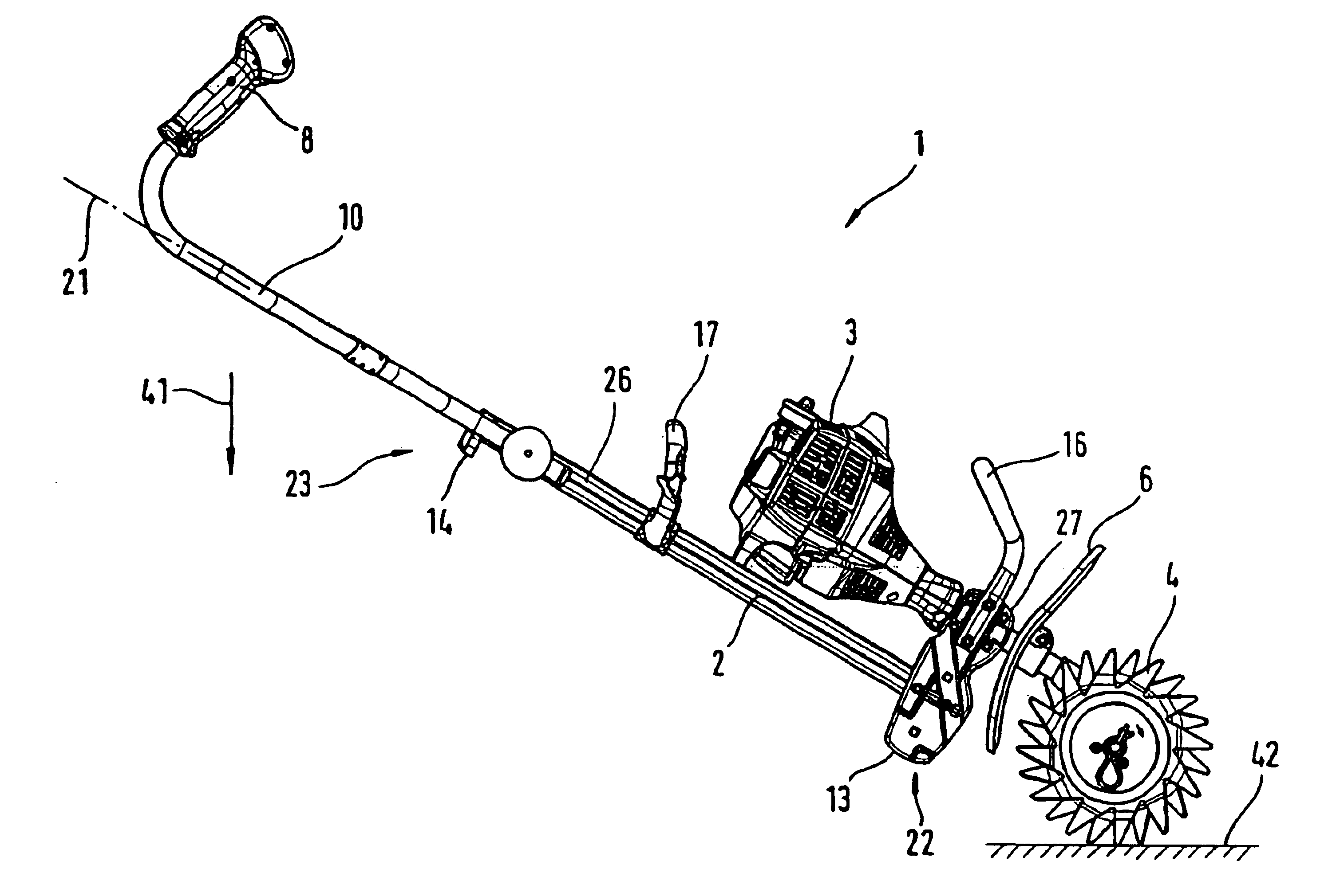
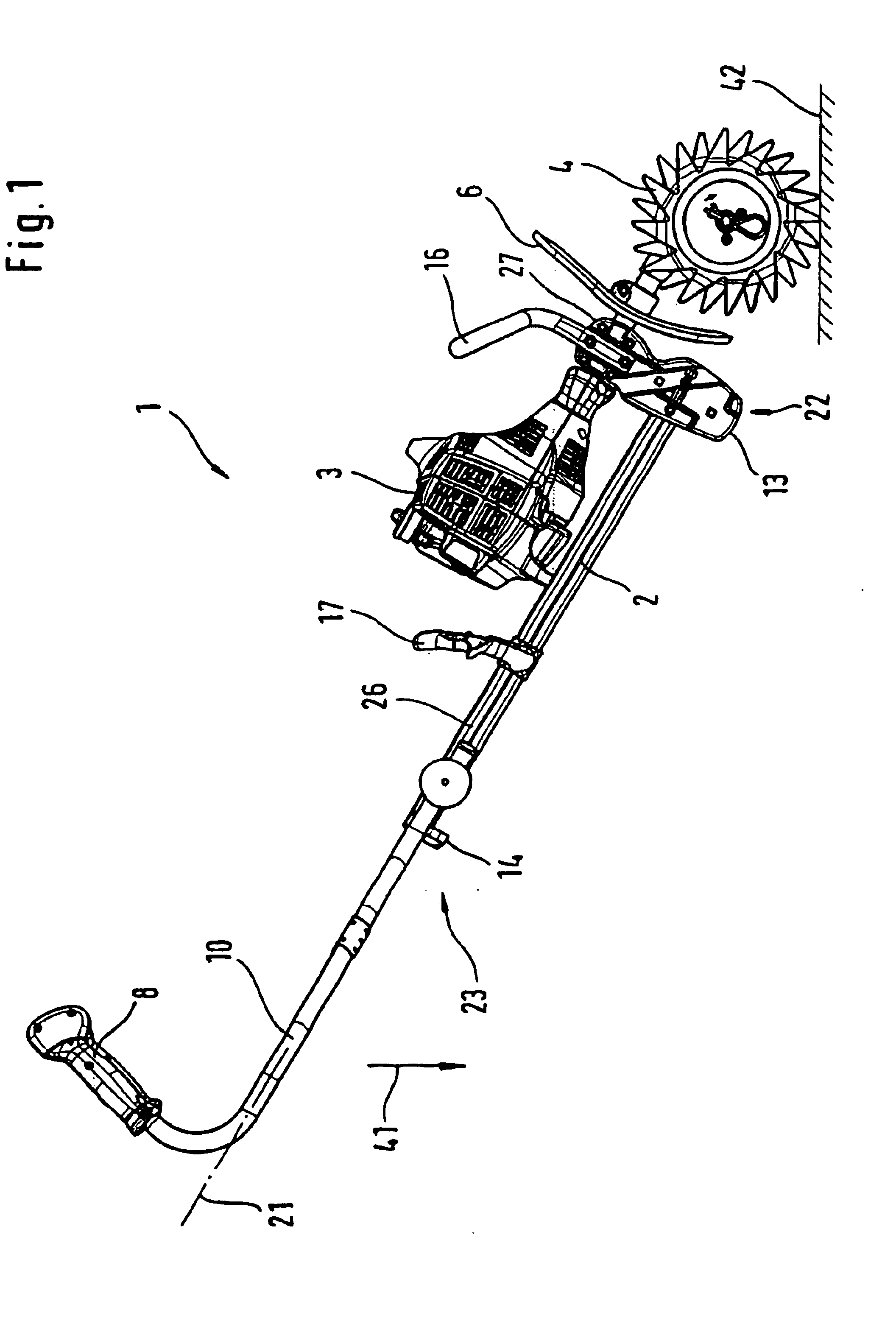
[0028]A motorized cultivator 1 is shown in its work position in FIG. 1 as an example of a portable handheld work apparatus. In the work position, the longitudinal direction 21 of the motorized cultivator 1 is inclined relative to the effective direction 41 of the gravitational force and is inclined, for example, at an angle between 20° and 80°. The motorized cultivator 1 has a frame 2 which extends essentially in the longitudinal direction 21 of the cultivator 1. The frame 2 is formed by a rod 26 having one end 22 at which a mount 27 is mounted with the mount running transversely to the rod 26. A drive motor 3 is fixed on the mount 27 and the drive shaft of the drive motor passes through this mount and drives the cultivator blade units 4 via a gear case 5 shown in FIG. 3. The blade units 4 lie on the ground surface 42 to be worked. The drive motor 3 is supported on the rod 26 at the end facing away from the mount 27. A protective shield 6 is mounted between the blade units 4 and the...


PUM


Abstract

A portable handheld work apparatus, such as a motorized cultivator (1) or the like, includes a frame (2) which extends essentially in the longitudinal direction (21) of the work apparatus. A drive motor (3) is fixed at one end (22) of the frame (2) and a work tool is driven by this drive motor. The opposite-lying end (23) includes at least a handle (7, 8) for guiding the work apparatus during the operation thereof. In order to make possible an ergonomic work posture of the operator, the handle (7, 8) lies facing away upwardly from the ground surface (42) in the work position of the motorized work apparatus. The work position is a position in which the work tool lies on the ground surface (42) to be worked.

Description

FIELD OF THE INVENTION[0001]The invention relates to a portable handheld work apparatus such as a motorized cultivator or the like.BACKGROUND OF THE INVENTION[0002]German patent publication 296 19 177 discloses a portable handheld motorized cultivator which includes a rod having first and second ends. A motor and a hoe blade are mounted on the first end and a handle is mounted at the second end. With the motorized cultivator in the work position, the handle extends in a horizontal direction. From this, there results an ergonomically unfavorable work position.SUMMARY OF THE INVENTION[0003]It is an object of the invention to provide a work apparatus of the kind described above which can be handled comfortably.[0004]The portable, hand-guided work apparatus of the invention defines a longitudinal axis and includes: a frame extending substantially in the direction of the longitudinal axis; the frame having a first end and a second end lying opposite the first end; an assembly including: ...

Claims


Application Information

Patent Timeline
Patent Type & Authority Patents(United States)
IPC IPC(8): A01B1/00A01B1/06A01B33/02A01B33/00B62B5/00B62B5/06
CPCA01B33/027
Inventor ZERRER, GERHARDLANGHANS, KLAUSKRAMER, JOCHENSTARK, THOMASVOGTLE, MICHAELMAYER, GUNTER
Owner ANDREAS STIHL AG & CO KG
Why Eureka
Try Eureka