Firearm handgrip adapter

a technology for handgrips and firearms, applied in the field of firearms, can solve the problems of difficult control, uncomfortable handgrip designs of early style handguns, and difficult control

Inactive Publication Date: 2015-04-21
HOVEY DAVID C
View PDF35 Cites 28 Cited by
  • Summary
  • Abstract
  • Description
  • Claims
  • Application Information

AI Technical Summary

Benefits of technology

[0042]It is another object of this invention is to provide a removably mounted handgrip that is mounted to the fore arm stock that can pivot clockwise or counter clockwise to comfortably accommodate the shooters support arm handgrip, whether left handed or right handed, and be easily locked in position to maintain stability while shooting and subsequently unlocked when it is desired to change the pivot angle of the handgrip.
[0043]Another object of this invention is to provide a forward handgrip that ergonomically assists in providing to the support arm enhanced pulling power to increase shoulder stock pressure to the shoulder to provide more control while shooting.
[0044]Yet another object of this invention is to provide the shooters aiming and support hand with an ergonomically comfortable handgrip similar to that available for the shooting hand.
[0045]Still another object of this invention is to provide any shooter with the capability of installing functionally and esthetically matching handgrips on the forward support portion and rear shooting portion of the firearm that are ergonomically comfortable.
[0046]All of the foregoing objects as well as others are achieved by the firearm handgrip adapter of this invention. Broadly, this invention is directed to a handgrip apparatus for mounting a handgrip on a forward portion of a firearm, for example a Picatinny rail under the barrel of an assault rifle. The apparatus includes an elongated mount having an upper portion with a clamp means for removably engaging the forward portion, e.g., rail, of the firearm. The handgrip, e.g., a vertical pistol handgrip, is symmetrical about a Vertical Plane passing through the handgrip. The distal portion of the handgrip, i.e., the “butt” portion that is gripped by the shooter, is offset in the Vertical Plane from the proximal portion of the handgrip. A pivot means connects the lower portion of the mount to the proximal portion of the handgrip to permit the pivoting of the Vertical Plane to varying pivot angles on either side of the Central Axis of the barrel. A lock means locks and unlocks the pivot means to lock the handgrip in a comfortable position at a selected pivot angle. The handgrip apparatus provides the ability of a left handed or right handed shooter to adjust the handgrip to a comfortable position while using the firearm. The handgrip apparatus may also be positioned at varying locations along the length of the forward portion of the firearm.

Problems solved by technology

Such known firearms tend to force the shooter's wrists into unnatural positions, which if continued for extended periods of time, becomes very uncomfortable.
Early style handguns had equally uncomfortable handgrip designs.
As is well known to firearm enthusiasts, large caliber and other automatic firearms are often difficult to control when firing, with a lack of control often resulting in muzzle rise which can cause the marksman to shoot wildly or above an intended point of aim or target.
Such handgrips are useful, but not aesthetically desirable.
However, such a fixed in-line forearm handgrip on this submachine gun is extremely awkward to grasp properly, particularly when a cylindrical drum magazine is attached.

Method used


Image

  • Firearm handgrip adapter
  • Firearm handgrip adapter
  • Firearm handgrip adapter

Examples


embodiment i

Elements in

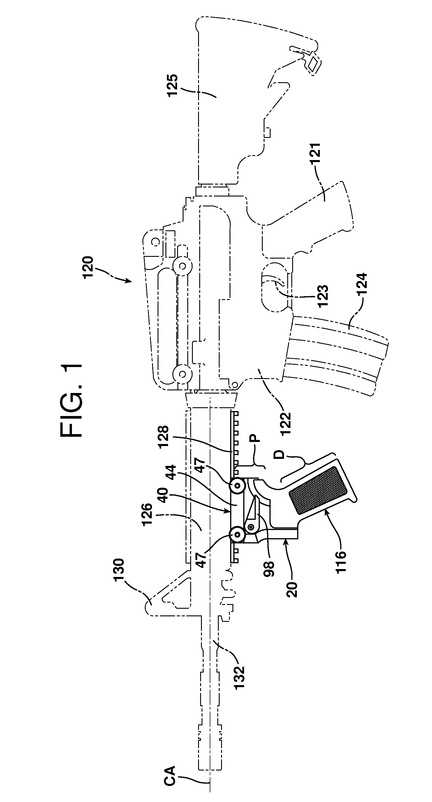
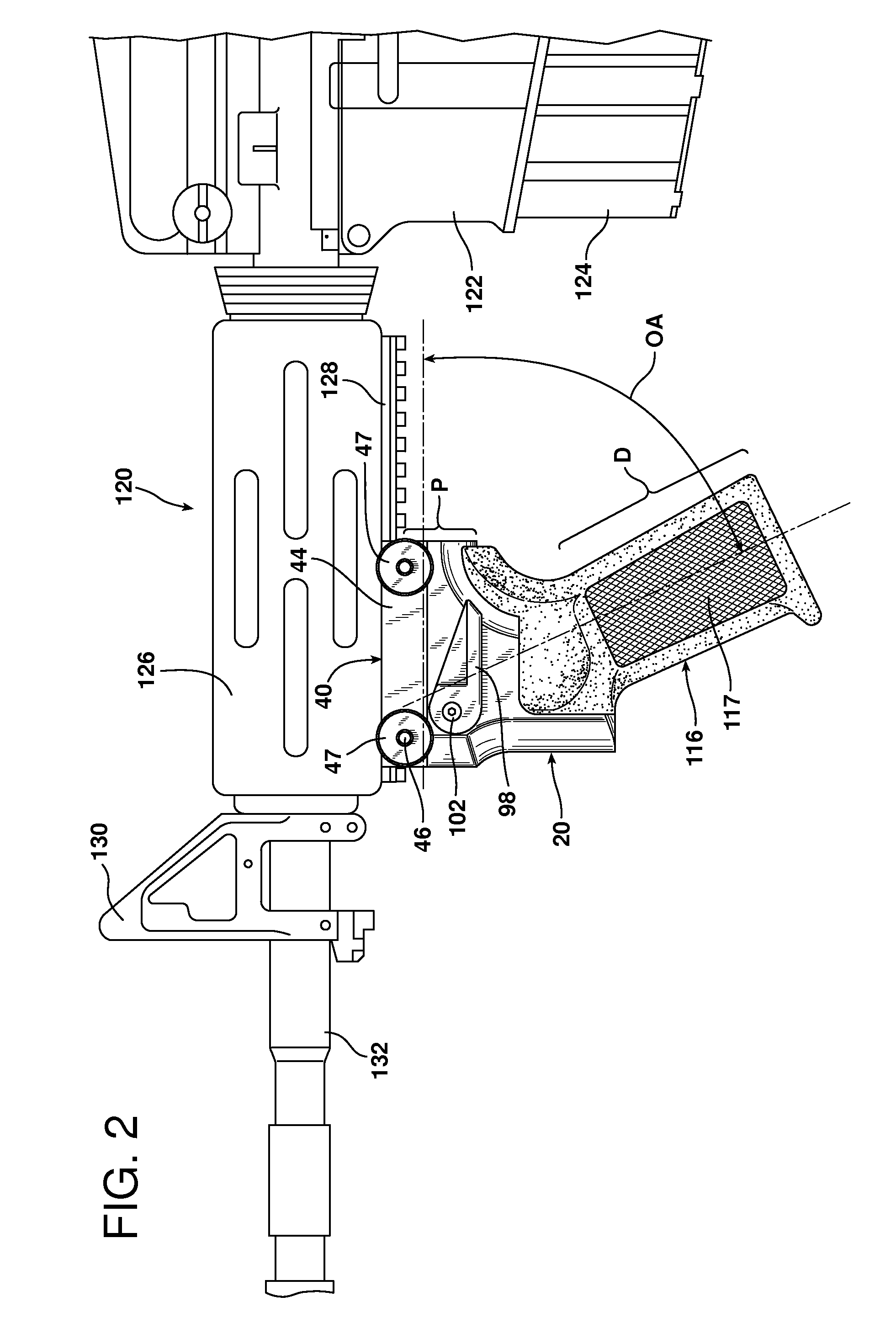
[0132]P proximal portion of handgrip 116[0133]D distal end of handgrip 116[0134]VP Vertical Plane passing through handgrip 116[0135]CA Central Axis of barrel 132[0136]OA offset pivot angle (shown in FIGS. 2 and 19)[0137]20 hand grip apparatus[0138]22 hole for pivot pin 84[0139]24 threaded holes for screws 70 for securing cover plate 68[0140]26 boss for mounting handgrip 116[0141]28 screw receptacle for securing handgrip 116 with retaining screw 118[0142]34 finger hold[0143]40 rail mount[0144]42 stationary jaw of rail mount 40[0145]43 interlocking surfaces of jaws 42, 44[0146]44 clamping jaw of rail mount 40[0147]45 dove-tailed rail engaging surface[0148]46 tightening screws for connecting and stationary jaw 42 and clamping jaw 44[0149]47 knurled locking nuts for tightening screws 46[0150]60 lock connector[0151]62 lock connector tooth[0152]64 screw for securing rail mount 40 through lock connector 60 to handgrip mount 20[0153]66 through hole in stationary jaw 42 for screw ...

embodiment ii

Elements in

[0193]P proximal portion of handgrip 116[0194]D distal end of handgrip 116[0195]VP Vertical Plane passing through handgrip 116[0196]CA Central Axis of barrel 132[0197]200 handgrip apparatus[0198]202 boss for mounting handgrip 116[0199]204 swivel direction of handgrip[0200]210 lock connector for connecting rail mount 40 to pivoting hand grip mount 200 and securing the stationary pivot lock 218[0201]212 lock connector tooth[0202]216 through hole in rail mount 40 for screw 64[0203]218 stationary pivot lock[0204]220 engagement teeth of stationary pivot lock 218[0205]224 receptacle for screw 64[0206]226 engagement teeth on lever 226[0207]228 engagement spring[0208]230 lever for engaging and disengaging teeth 220, 226[0209]232 pivot post for lever 230[0210]234 axle for pivot post 234[0211]236 direction of lever 230[0212]238 spring latch for mounting one end of extension spring 242[0213]240 spring post for mounting the other end of extension spring 242[0214]242 extension spring

E...

embodiment iii

Elements in

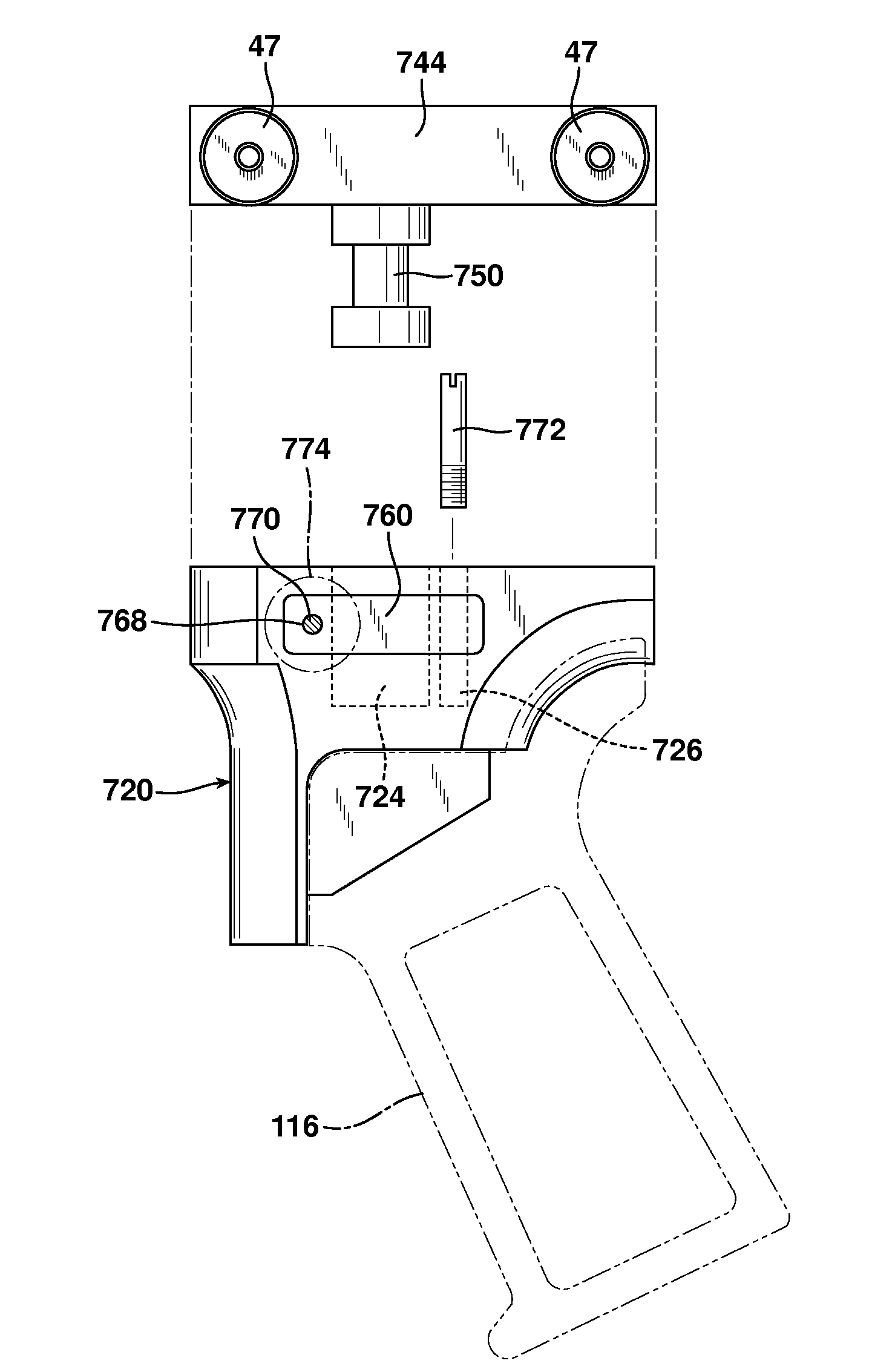
[0220]P proximal portion of handgrip 116[0221]D distal end of handgrip 116[0222]VP Vertical Plane passing through handgrip 116[0223]CA Central Axis of barrel 132[0224]300 handgrip apparatus[0225]302 stationary pivot lock[0226]303 teeth of stationary pivot lock 302[0227]304 retractable pivot lock[0228]305 handle for retractable pivot lock 304[0229]306 engagement teeth on retractable pivot lock 304[0230]308 single engagement spring[0231]310 spring channel for single engagement spring 308[0232]312 plurality of compression springs[0233]313 connecting rod connecting handle 305 and retractable pivot lock 304[0234]314 spring channels for multiple engagement springs 312[0235]315 shoulder of retractable pivot lock 304[0236]316 spring retainer rod for retractable pivot lock 304[0237]318 spring retainer rod for retractable pivot lock handle 305[0238]320 slot for retraction movement of retractable pivot lock 304[0239]322 spring stop for retractable pivot lock 304 and height spacer fo...


PUM


Abstract

An apparatus for mounting a handgrip on a forward portion of a firearm. The apparatus includes a mount having an upper portion with a clamp for removably engaging the firearm forward portion. The handgrip, e.g., a pistol handgrip, is symmetrical about a vertical plane passing through the handgrip. The distal portion of the handgrip is offset in the vertical plane from the proximal portion of the handgrip. A pivot means connects the lower portion of the mount to the proximal portion of the handgrip to permit the pivoting of the vertical plane to varying angles on either side of the central axis of the barrel. A lock means locks and unlocks the pivot means to lock the handgrip in position at a selected pivot angle. The apparatus provides the ability of a left handed or right handed shooter to adjust the handgrip to a comfortable position while using the firearm.

Description

BACKGROUND OF THE INVENTION[0001]1. Field of the Invention[0002]The present invention relates to firearms and specifically to a handgrip apparatus for mounting on a forward portion of a firearm, particularly one having a rail such as a Picatinny rail. More particularly, this invention relates to a vertical style handgrip or pistol grip that is adapted to be mounted on the forward portion of a firearm, preferably on a Picatinny rail, that allows for the selective movement of the handgrip not only along the length of the rail, but for different angular orientations of the handgrip to the rail or barrel to comfortably accommodate a left handed or right handed shooter or a shooter with an atypical hand / arm angulation. The handgrip apparatus permits the handgrip to pivot to an ergonomically acceptable position to accommodate the hand and then be locked in such position prior to use.[0003]2. Description of the Related Art[0004]Referring for general background to FIGS. 1 and 2, most huntin...

Claims


Application Information

Patent Timeline
Patent Type & Authority Patents(United States)
IPC IPC(8): F41C23/00F41C23/16F41G11/00
CPCF41C23/16F41G11/003
Inventor HOVEY, DAVID C.
Owner HOVEY DAVID C
Why Eureka
Try Eureka