Projector

a projector and projection screen technology, applied in the field of projectors, can solve the problems of trapezium distortion of the projected image, difficult adjustment, and the state of the case itself, and achieve the effect of facilitating the adjustment of the set up angl

Inactive Publication Date: 2005-04-12
NEC DISPLAY SOLUTIONS LTD
View PDF8 Cites 49 Cited by
  • Summary
  • Abstract
  • Description
  • Claims
  • Application Information

AI Technical Summary

Benefits of technology

According to another embodiment of the invention, the projector further comprises driving means for driving the reflecting mirror for automatically adjusting the set up angle. Accor

Problems solved by technology

Therefore, in order to change the position of the projected image, the set up state of the case itself needs to be changed which is difficult to adjust.
Furthermore, when the case of the conventional projector where it is tilted to adjust t

Method used


Image

  • Projector
  • Projector
  • Projector

Examples


embodiment 1

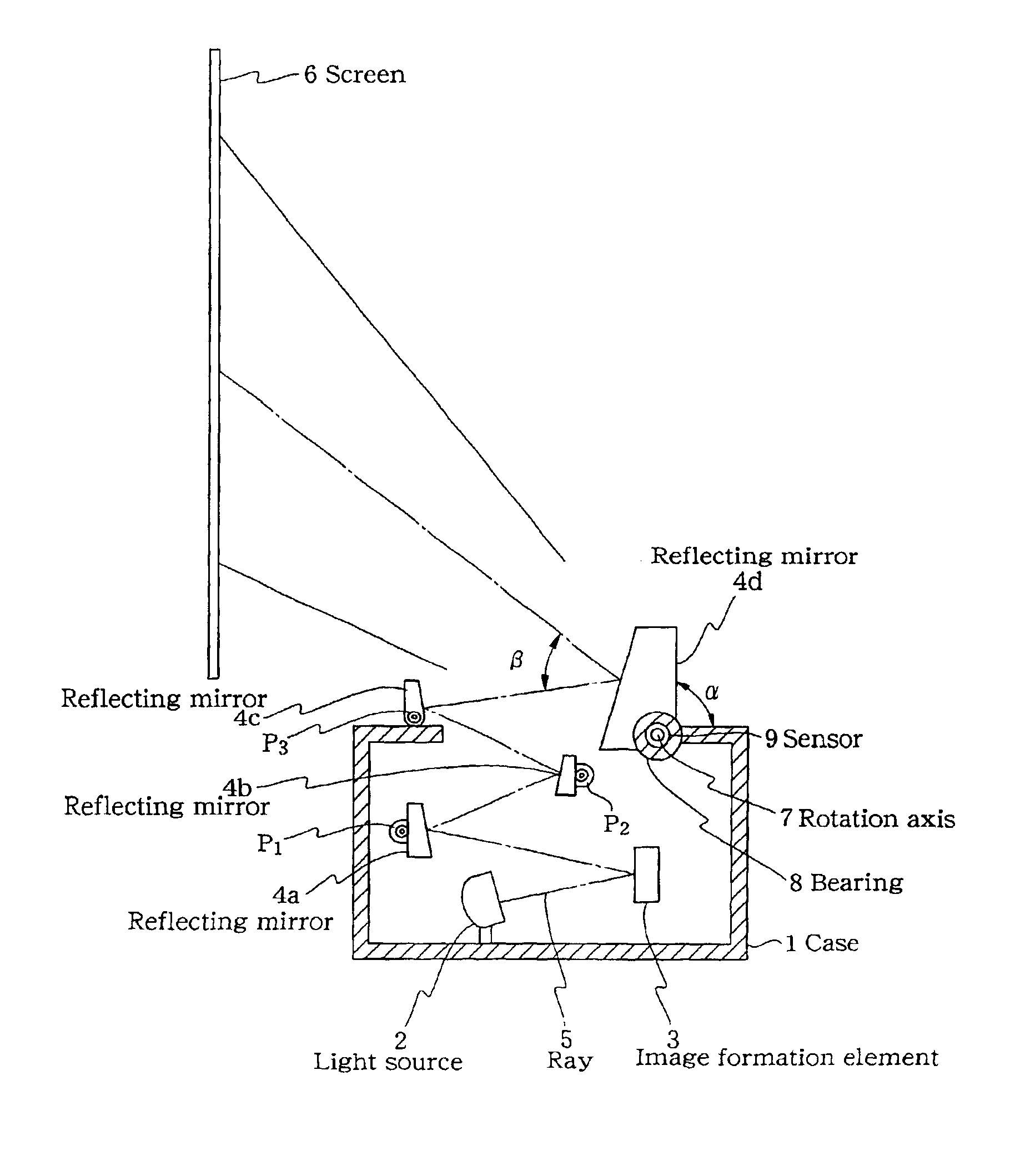
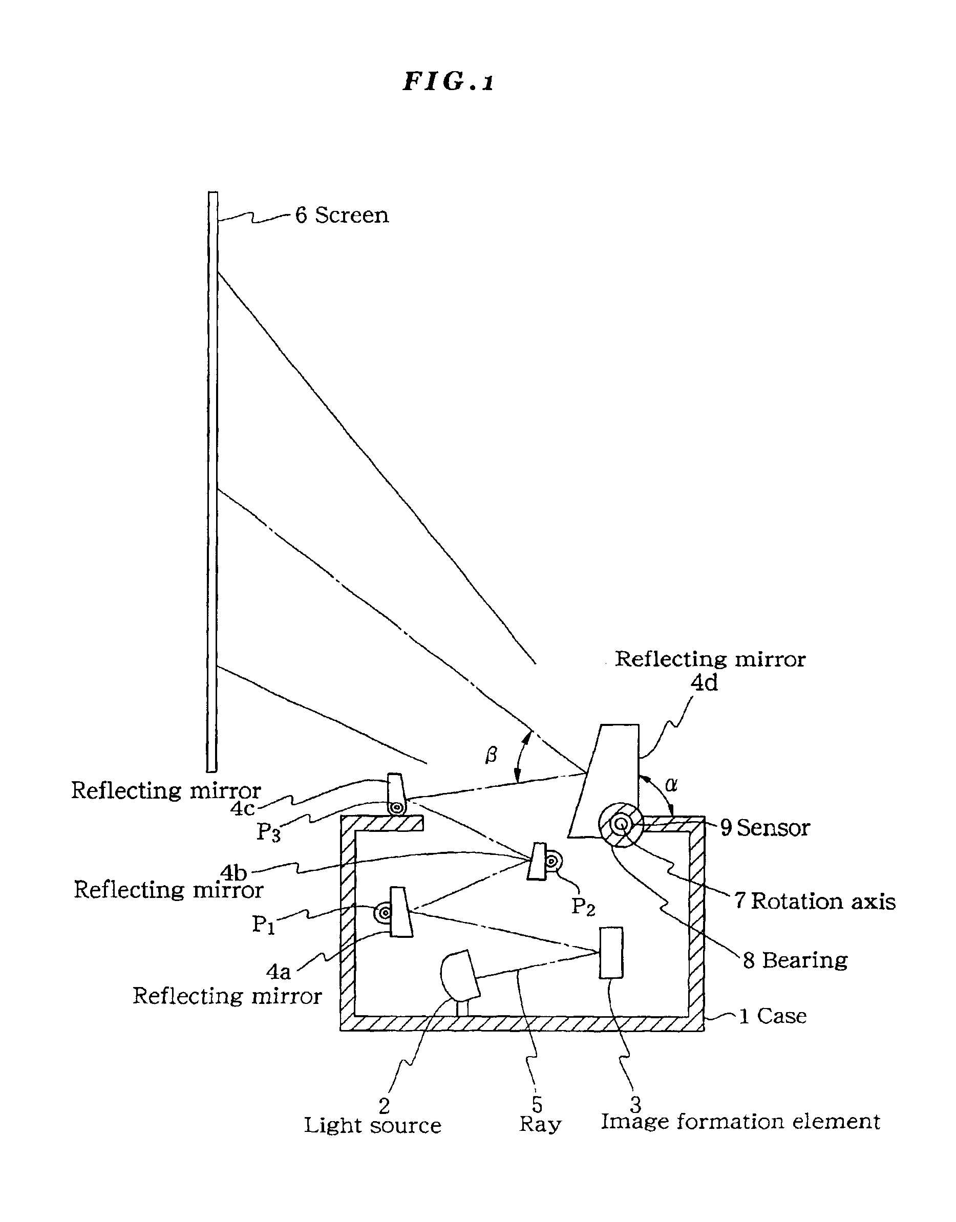
First, a projector according to a first embodiment of the invention will be described. As shown in FIG. 1, the projector according to the present embodiment is provided with a case 1 which serves as a main body of the projector and in which a light source 2, an image formation element 3 and a projection optical system for projecting a ray 5 modulated by the image formation element 3 are arranged. The projection optical system is provided with flat reflecting mirrors 4a, 4b, 4c and 4d as optical elements. A ray emitted from the light source 2 passes through the image formation element 3 and an imaging lens (not shown) of the projection optical system, is reflected by the reflecting mirrors 4a to 4d and is finally projected on a screen 6.

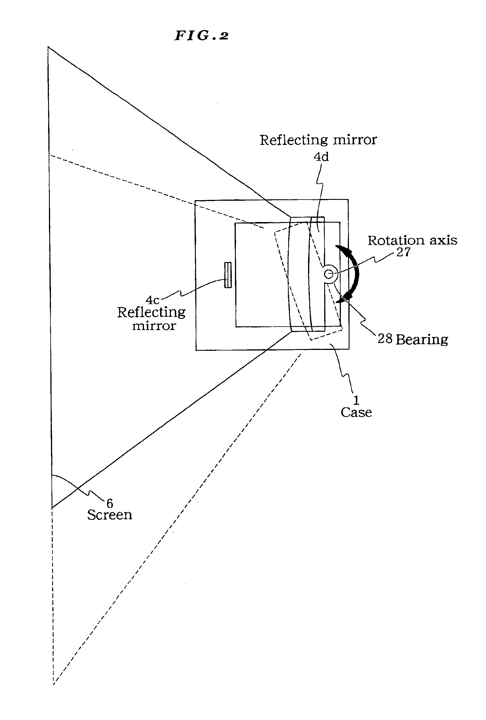
Among the reflecting mirrors 4a to 4d, the mirrors 4a, 4b and 4c are completely secured to the case 1. The reflecting mirror 4d has a rotation axis 7 which is inserted into a bearing 8 of the case 1. Accordingly, the reflecting mirror 4d is capable of...

embodiment 2

Next, a projector according to a second embodiment of the invention will be described. FIG. 4 is a schematic view showing a structure of the projector of the present embodiment. As shown in FIG. 4, the projector according to the present embodiment is provided with a case 41 in which a light source 42, an image formation element 43 and a projection optical system for projecting a ray 45 on a screen 46 are arranged. The projection optical system is provided with reflecting mirrors 44a, 44b, 44c and 44d as optical elements. A light 45 emitted from the light source 42 passes through the image formation element 43 and an imaging focusing lens (not shown) of the projection optical system, is reflected by the reflecting mirrors 44a to 44d and is finally projected on the screen 46.

The reflecting mirrors 44a, 44b and 44c are completely secured to the case 41. Only the reflecting mirror 44d is provided with an adjustment mechanism which allows the reflecting mirror on the case 41 to move in b...


PUM


Abstract

A reflecting mirror 4d has a rotation axis 7 which is inserted into a bearing 8 of a case 1. Accordingly, the reflecting mirror 4d is capable of rotating with respect to the case 1 and only the reflecting mirror 4d is capable of adjusting the set up angle α made with the case 1. When the set up angle is changed, the reflecting angle of the projected ray on the reflecting mirror 4d is also changed. Therefore, the launching angle of the projected ray 5 with respect to the case 1 can be adjusted.

Description

FIELD OF THE INVENTIONThe present invention relates to a projector which projects a light from an image formation element on a screen with a projection optical system. More particularly, the present invention relates to a projector which is capable of adjusting a position of an image projected on a screen.BACKGROUND OF THE INVENTIONVarious types of displaying devices have been proposed heretofore. In particular, a projector for enlargement projection of a color picture is proposed as a displaying device for a large-sized screen, in which small mirror surface elements are arranged into a plane according to pixels and in which a specular-reflective-type optical modulator, or an image formation element, utilizing reflection of each mirror surface element is used as a picture source.FIG. 5 is a schematic view showing a structure of a conventional projector. Referring to FIG. 5, the conventional projector is provided with a case 51 in which a light source (luminous source) 52, an image f...

Claims


Application Information

Patent Timeline
IPC IPC(8): G03B21/28G03B21/00G02B27/18G03B21/14H04N5/74
CPCG03B21/28
Inventor FUKUNAGA, HIROAKIFURUICHI, KUNITAKA
Owner NEC DISPLAY SOLUTIONS LTD
Why Eureka
Try Eureka