Non-contact power supplying apparatus

A non-contact power supply and electric power technology, applied in circuit devices, along the running track devices, circuits, etc., to achieve strong electromagnetic coupling, high efficiency, significant effect and excellent effect

Active Publication Date: 2008-05-14
SHOWA AIRCRAFT INDUSTRY +1
View PDF2 Cites 48 Cited by
  • Summary
  • Abstract
  • Description
  • Claims
  • Application Information

AI Technical Summary

Problems solved by technology

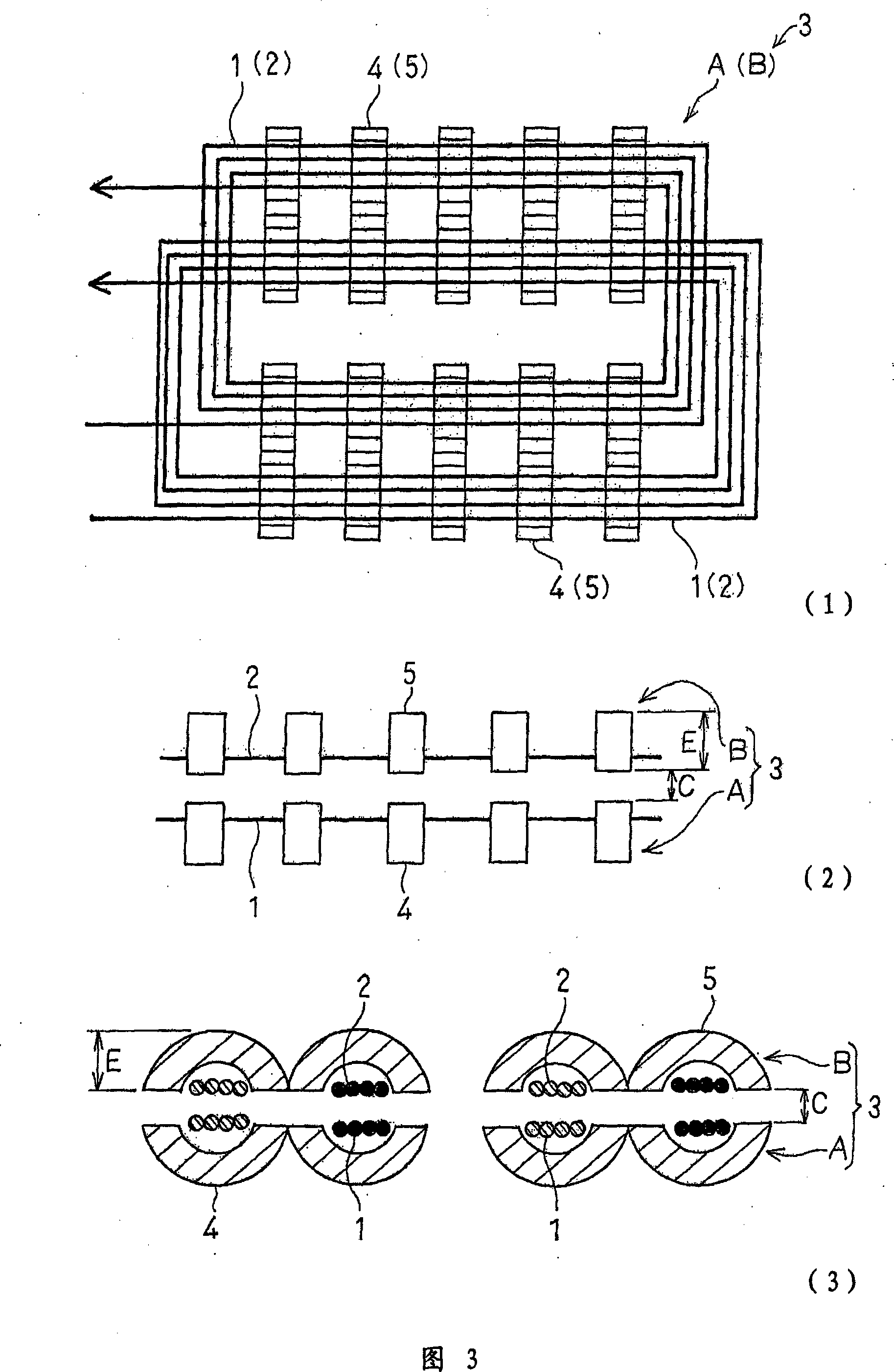
As shown in (2) and (3) of Figure 3, the thickness increases by the amount correspondi

Method used


Image

  • Non-contact power supplying apparatus
  • Non-contact power supplying apparatus
  • Non-contact power supplying apparatus

Examples


Embodiment Construction

[0068] Hereinafter, the contactless power supply device of the present invention will be described in detail based on the preferred embodiments for implementing the present invention shown in the accompanying drawings.

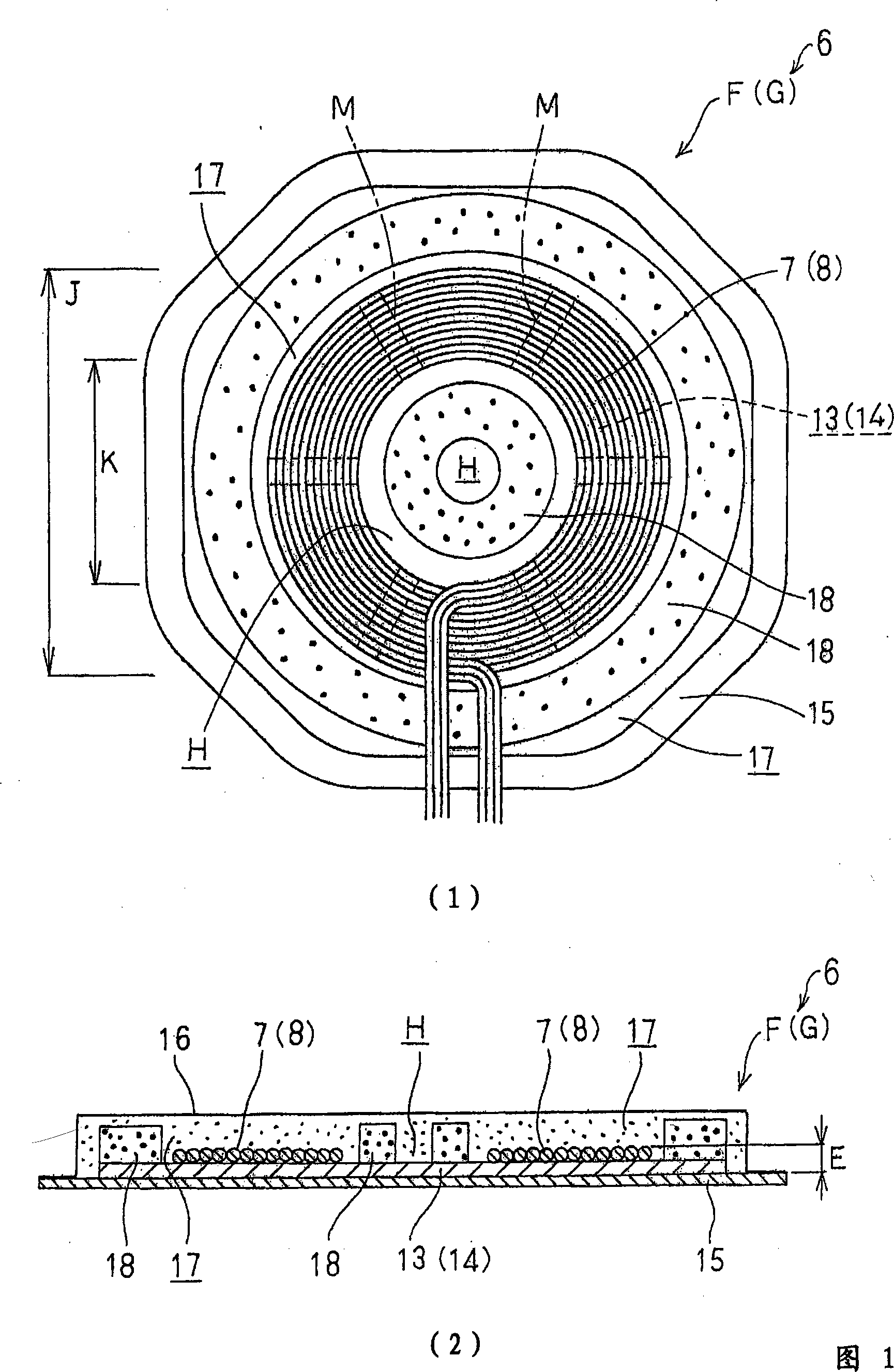
[0069] FIG. 1 and FIG. 2 are for the description of the preferred embodiment for carrying out the present invention. 1 is a plan view of the primary side, that is, a view viewed from above (it is also a plan view of the secondary side, that is, a view viewed from above), and view (2) is a view of the primary side and the secondary side. A view is a cross-sectional view viewed from the front (side view, that is, viewed from a lateral direction).

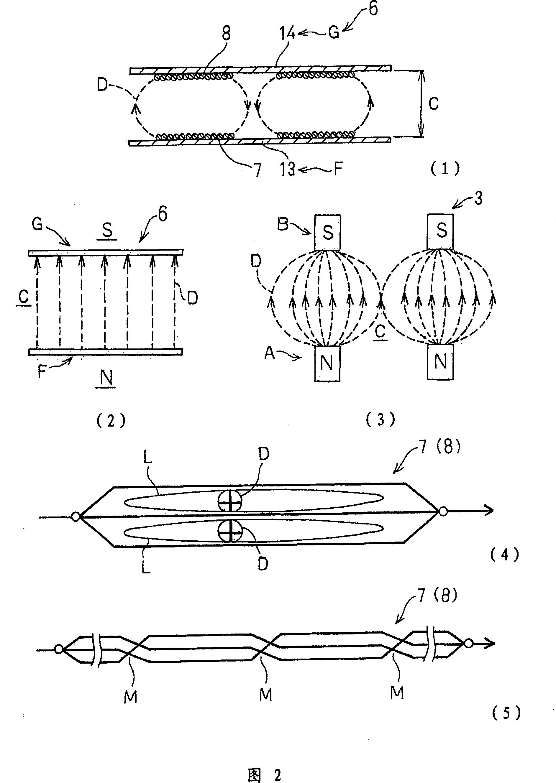
[0070] Fig. 2 (1) is a front view of the electromagnetic coupling, that is, a cross-sectional explanatory view viewed from the front (side view, that is, viewed from a lateral direction), (2) is a front view of the magnetic flux distribution, and (4) Fig. An explanatory plan view of the eddy current, and FIG. (5) is ...


PUM


Abstract

This non-contact electric power supply device 6 is used to charge, for example, a battery of an electric vehicle, and electric power is supplied from a primary side, i.e., a primary coil 7 on an electric power supply side to a secondary side, i.e., a secondary coil 8 on an electric reception side based on a mutual induction effect of electromagnetic induction. The primary coil 7 and the secondary coil 8 are flatly and spirally wound in one plane, respectively, (by) making a plurality of parallel conducting wires a set and are twisted at a regular pitch interval along the way. A primary magnetic core 13 and secondary magnetic core 14 on which the primary coil 7 and the secondary coil 8 are disposed are made of ferrite and the like and are formed in a tabular shape. Outer surfaces of the primary coil 7 and the primary magnetic core 13 and outer surfaces of the secondary coil 8 and the secondary magnetic core 14 are covered and secured by molded resin 17, respectively. Foamed materials 18 are mixed in the molded resin 17.

Description

technical field [0001] The present invention relates to a contactless power supply device. That is, the present invention relates to a non-contact power supply device based on a mutual induction effect of electromagnetic induction. For example, it relates to a non-contact power supply device that charges the battery of a battery car from the outside in a non-contact manner. Background technique [0002] ( 1 ) of FIG. 4 is a perspective explanatory view for explaining the basic principle of a contactless power supply device of such a prior art. Regarding this basic principle, the conventional example is the same as that of the present invention. [0003] As shown in the same figure, there is known a non-contact power supply device 3 that supplies electric power from a primary coil to a secondary coil by mutual inductance of electromagnetic induction, and is used for charging a battery of a battery car, for example. [0004] That is, in the non-contact power supply device, ...

Claims


Application Information

Patent Timeline
IPC IPC(8): H02J17/00H01F38/14H01F17/04H01M10/44B60M7/00
CPCY02E60/12B60L53/12B60L2270/147H01F27/022H01F27/2871H01F27/36H01F38/14Y02T10/70Y02T10/7072Y02T90/14H01F5/003H02J50/10
Inventor 山本喜多男铃木义雄佐藤刚松木英敏佐藤文博
Owner SHOWA AIRCRAFT INDUSTRY
Why Eureka
Try Eureka