Firetube having thermal conducting passageways

a technology of thermal conductivity and firetube, which is applied in the direction of recuperative heat exchangers, stationary tubular conduit assemblies, steam boiler components, etc., can solve the problems of inefficient heat exchanger, loss of significant amount of available heat, loss of conventional u-tube firetubes,

Inactive Publication Date: 2012-06-14
CHADWICK ENERGY SERVICES
View PDF6 Cites 11 Cited by
  • Summary
  • Abstract
  • Description
  • Claims
  • Application Information

AI Technical Summary

Benefits of technology

[0011]Advantageously, where process fluids comprise emulsions of water and hydrocarbons having different coefficients causing them to expand and contract at different rates, the expansion and

Problems solved by technology

Use of round pipe to create the U-tube firetube results in a very inefficient heat exchanger as the surface area presented to the intended fluid is limited.
As a result, a significant amount of the available heat, imparted by the flame, is lost as hot exhaust ga

Method used


Image

  • Firetube having thermal conducting passageways
  • Firetube having thermal conducting passageways
  • Firetube having thermal conducting passageways

Examples


Embodiment Construction

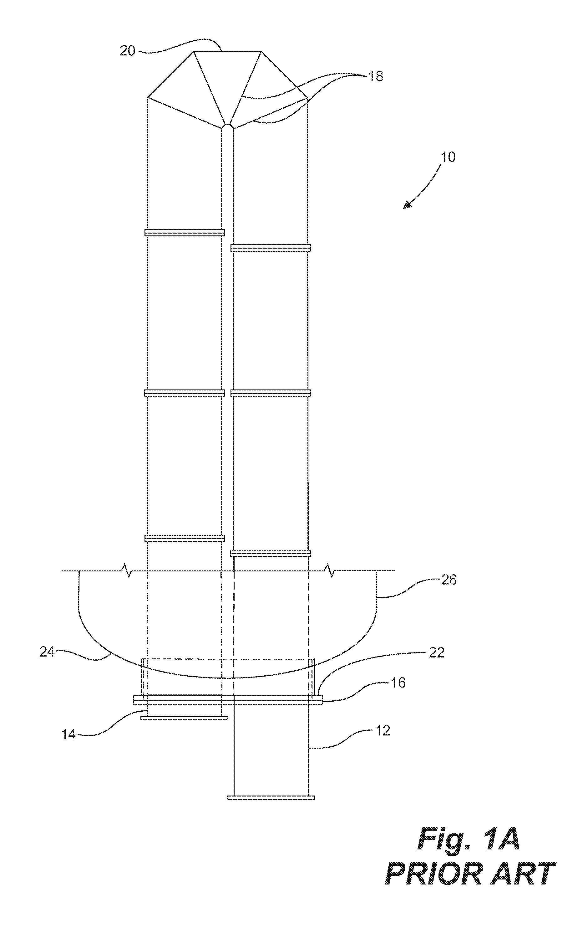
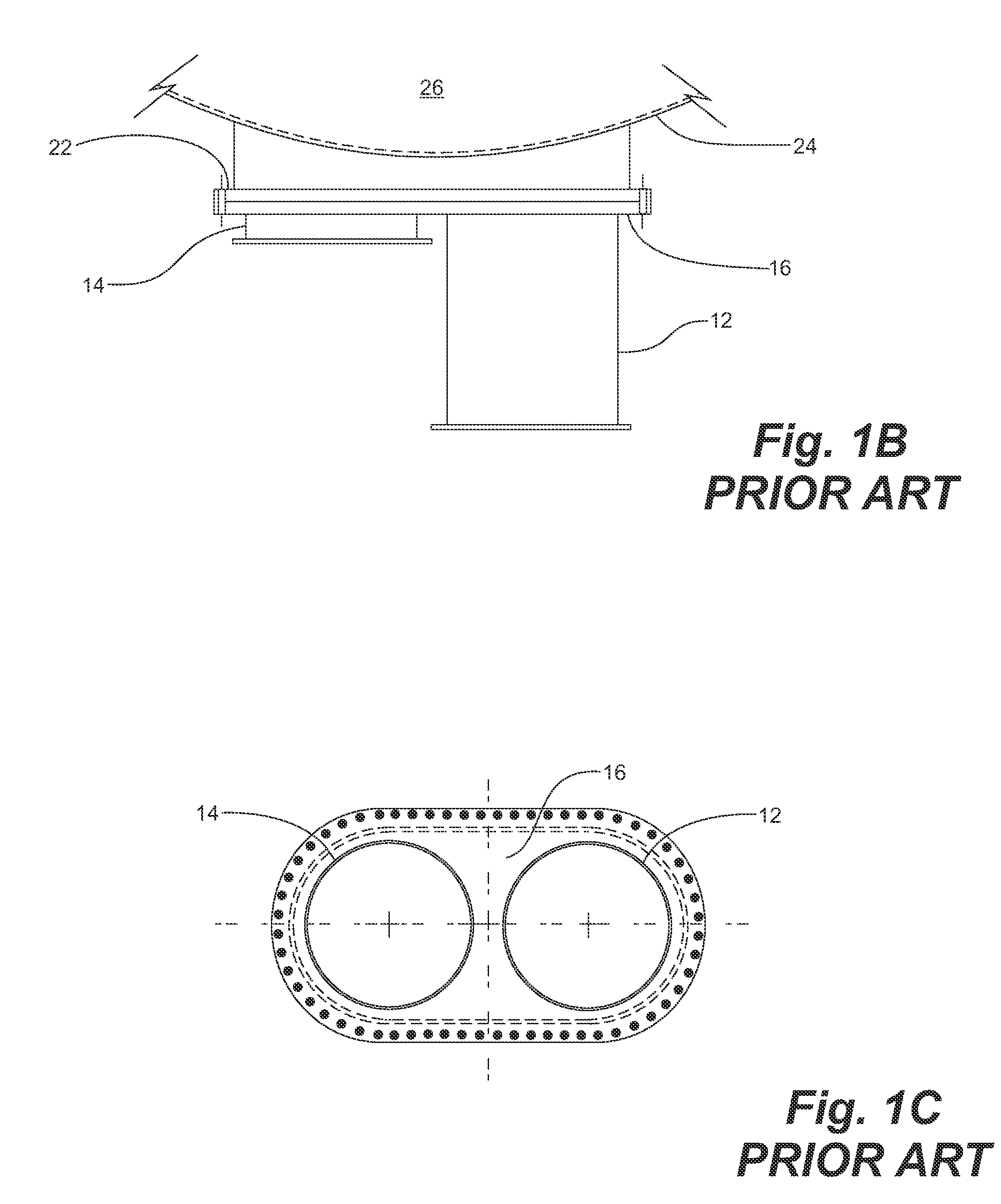
[0033]As shown in FIGS. 1A-1C, prior art firetubes 10 are generally U-shaped tubes, having a side-by-side gas inlet 12 and gas outlet 14 at a flanged connection 16 at a front wall 24 of vessel 26. The firetube 10 is generally manufactured from round, steel pipe which is welded together, using welded mitres 18 for forming the “U” at an end 20. The prior art firetube 10 is connected to a manway 22, typically obround in shape to accommodate the side-by-side inlet 12 and outlet 14. The gas inlet 12 connects therethrough to a burner (not shown) for receiving flame and hot exhaust gases therefrom. The outlet 14 connects to an exhaust stack (not shown) for exhausting waste gases therefrom. Flanged connections are typically used throughout.

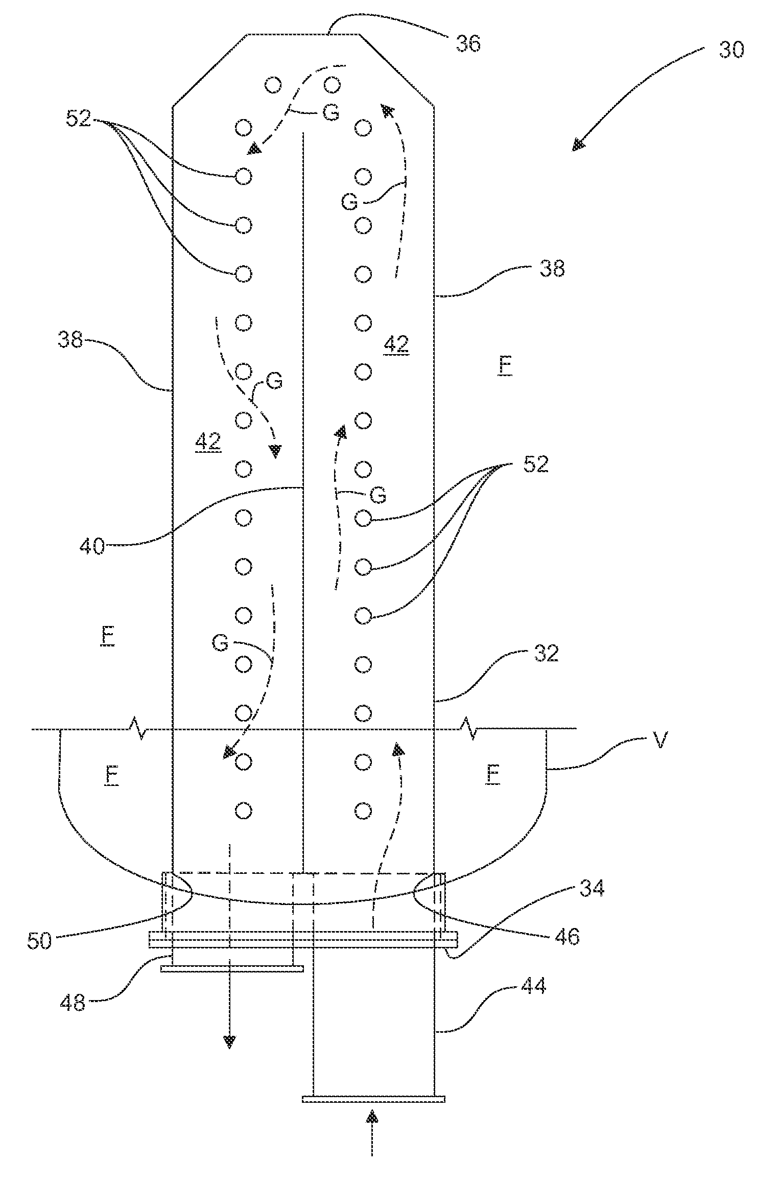
[0034]Firetubes, according to embodiments disclosed herein, can be incorporated in new heat exchange vessels or can be used to retrofit existing vessels to upgrade and enhance the efficiency of heat transfer therein. Heat transfer surface area is increase...


PUM


Abstract

A firetube is immersed in a fluid to be heated and transfers heat from hot gases flowing through the firetube to the fluid surrounding the firetube. The firetube has a plurality of thermally conductive passageways which extend through the firetube for increasing the surface area available for heat transfer. Fluid is conducted through the passageways by a thermosiphon effect resulting from a temperature differential in the vessel, the fluid below the firetube being cooler and denser than fluid above the heat exchanger.

Description

CROSS-REFERENCE TO RELATED APPLICATIONS[0001]This application claims the benefit of U.S. provisional application 61 / 422,810, filed Dec. 14, 2010, and U.S. provisional application 61 / 434,258, filed Jan. 19, 2011, the entirety of each of which is incorporated herein by reference.FIELD OF THE INVENTION[0002]Embodiments of the invention relate to indirect-fired and direct-fired heat exchangers and more particularly to firetubes installed in process vessels, the firetubes having enhanced surface area for heating process fluids.BACKGROUND OF THE INVENTION[0003]It is known to heat process fluids in a variety of vessels, such as ASME code process vessels, atmospheric bath heaters and tanks. Generally, a heat exchanger is fit within a vessel for heating fluids, such as those commonly handled in oilfield handling and refining operations.[0004]In the oilfield, U-shaped “firetubes”, referred to as U-tube firetubes or U-tubes, are common heat exchangers for use in vessels containing fluids to be...

Claims


Application Information

Patent Timeline
IPC IPC(8): F28F1/10F22B37/06
CPCF24H9/0026F28F2250/04F24H1/207F28D21/0003F28F13/06F28D7/06F28D7/12F24H9/0015
Inventor CHADWICK, THOMAS
Owner CHADWICK ENERGY SERVICES
Why Eureka
Try Eureka