Tool securing device and methods related thereto

a tool and securing device technology, applied in the field of magnetic tool securing devices, can solve the problems of not enabling quick and easy access, prone to breakage of loops, bulky hammer securing devices, etc., and achieve the effect of quick and easy removal of tools

Inactive Publication Date: 2012-06-14
PK PRODS
View PDF6 Cites 159 Cited by
  • Summary
  • Abstract
  • Description
  • Claims
  • Application Information

AI Technical Summary

Benefits of technology

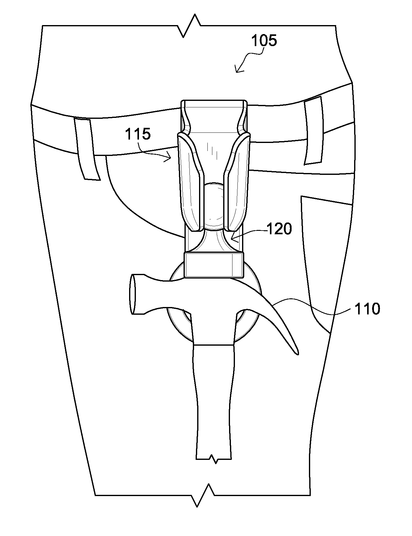
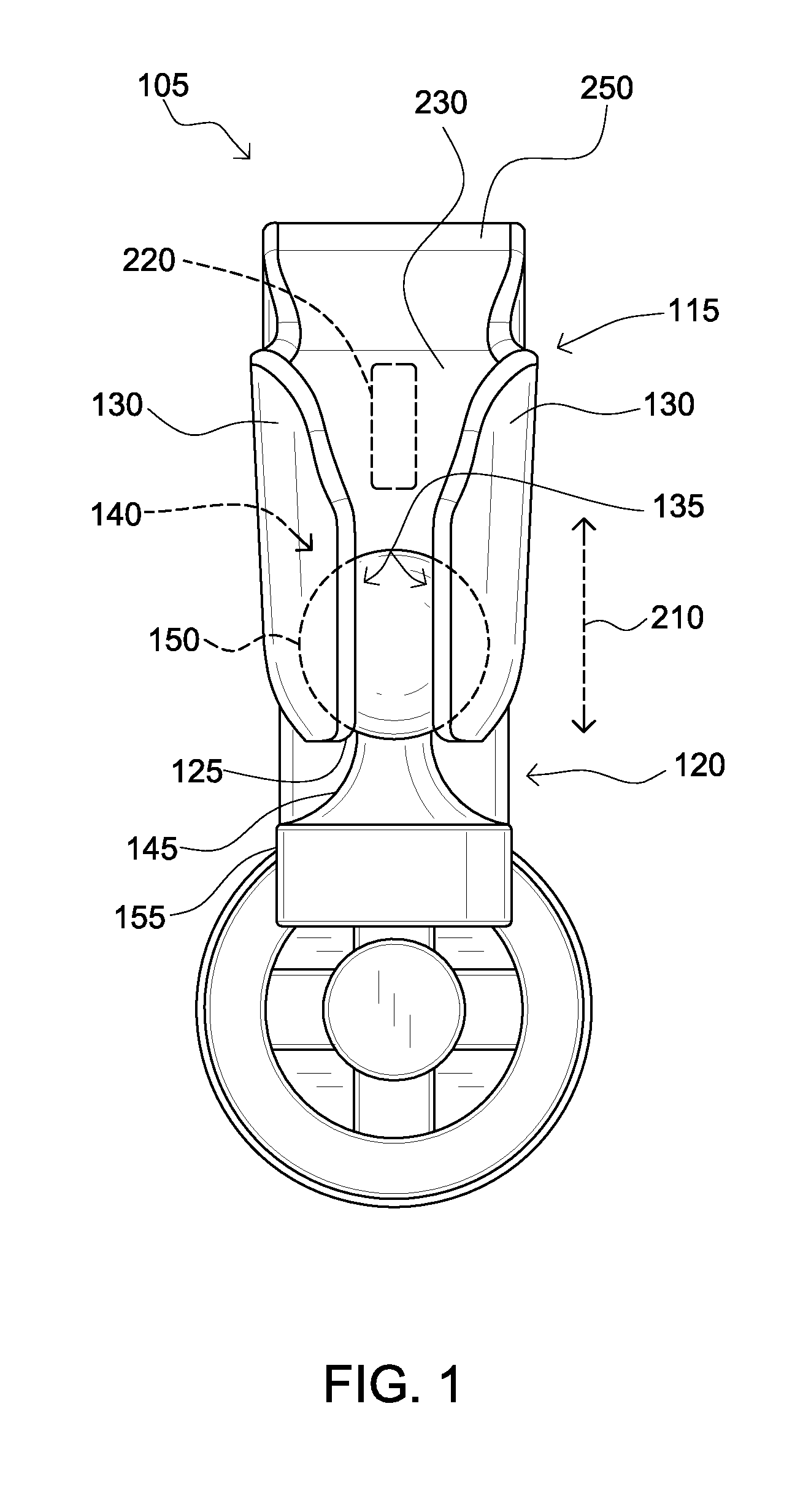
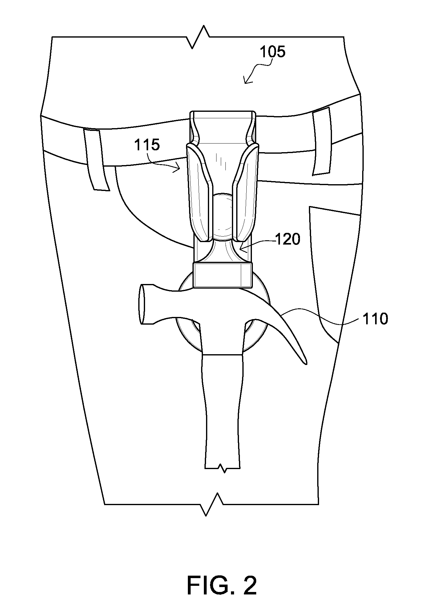
[0016]The present invention has been developed in response to the present state of the art, and in particular, in response to the problems and needs in the art that have not yet been fully solved by currently available tool securing devices. Accordingly, the present invention has been developed to provide a device for removably securing a tool, such as a hammer, that may enable a user to quickly and easily remove the tool and that is not bulky or difficult to move.

Problems solved by technology

However, over time the leather would dry up and over time the loop would be susceptible to breakage.
However, these hammer securing devices typically are bulky and do not enable quick and easy access to the hammer for a user.
Furthermore, typically many hammer securing devices includes latches, fasteners, deep pockets in a tool belt, or other securing implements that typically require a user to expend effort in removing the hammer for use.
Additionally, the hammer securing devices of the prior art typically require a user to lift up and / or drop the shaft of the hammer through a loop.
The inventions heretofore known suffer from a number of disadvantages, some of which include: tools secured to a holder are not easily accessible and / or easily removable from the holder, the holder is bulky and / or difficult to move / access / utilize / engage, being expensive, being heavy, being poorly positioned, and / or the holder is uncomfortable for a user and / or otherwise restricts motion of a user's body.

Method used


Image

  • Tool securing device and methods related thereto
  • Tool securing device and methods related thereto
  • Tool securing device and methods related thereto

Examples


Embodiment Construction

[0031]For the purposes of promoting an understanding of the principles of the invention, reference will now be made to the exemplary embodiments illustrated in the drawing(s), and specific language will be used to describe the same. It will nevertheless be understood that no limitation of the scope of the invention is thereby intended. Any alterations and further modifications of the inventive features illustrated herein, and any additional applications of the principles of the invention as illustrated herein, which would occur to one skilled in the relevant art and having possession of this disclosure, are to be considered within the scope of the invention.

[0032]Reference throughout this specification to an “embodiment,” an “example” or similar language means that a particular feature, structure, characteristic, or combinations thereof described in connection with the embodiment is included in at least one embodiment of the present invention. Thus, appearances of the phrases an “em...


PUM


Abstract

A device for removably securing a tool, the device comprising: a receiving member configured to provide support; and a securing member selectably coupleable to the receiving member and configured to removably secure the receiving member to the tool. The securing member comprises a magnet, the magnet disposed on an underside portion of the securing member.

Description

CROSS-REFERENCE TO RELATED APPLICATIONS[0001]This invention claims priority, under 35 U.S.C. §120, to the U.S. Provisional Patent Application No. 63 / 328,977 filed on Apr. 28, 2010, which is incorporated by reference herein in its entirety.BACKGROUND OF THE INVENTION[0002]1. Field of the Invention[0003]The present invention relates to devices for securing tools and methods related thereto, more specifically to magnetic tool securing devices and methods related thereto.[0004]2. Description of the Related Art[0005]In the related art, it has been known to use various devices and methods to secure tools such as, hammers, power tools, screwdrivers, and the like, to a person or object. Typically these devices include trays, pockets, or other holders that are designed to retain one or more tools. Some devices are configured to be more mobile and easier for a user to carry with them while working, while others are more optimal for use attached to an immovable object such as a wall. In most c...

Claims


Application Information

Patent Timeline
Patent Type & Authority Applications(United States)
IPC IPC(8): A45F5/14
CPCA45F2200/0575A45F5/021
Inventor KAHN, PETER
Owner PK PRODS
Why Eureka
Try Eureka