Three-Dimensional Tracking of a User Control Device in a Volume

a technology of user control device and volume, applied in the field of spatial tracking, can solve the problems of system prone to interference, current system lack of precision, limited capabilities of current system,

Active Publication Date: 2012-06-28
INFINITE Z
View PDF2 Cites 60 Cited by
  • Summary
  • Abstract
  • Description
  • Claims
  • Application Information

AI Technical Summary

Problems solved by technology

However, current systems are limited in their capabilities.
For example, gross movement may be tracked, but for slow or constant velocity movements, the current systems lack precision.
Still other systems may be prone to interference from magnetic devices and may not be able to consistently identify true north.
Finally, some systems utilize a large form factor enclosure that may not allow precise movement control.

Method used


Image

  • Three-Dimensional Tracking of a User Control Device in a Volume
  • Three-Dimensional Tracking of a User Control Device in a Volume
  • Three-Dimensional Tracking of a User Control Device in a Volume

Examples


Embodiment Construction

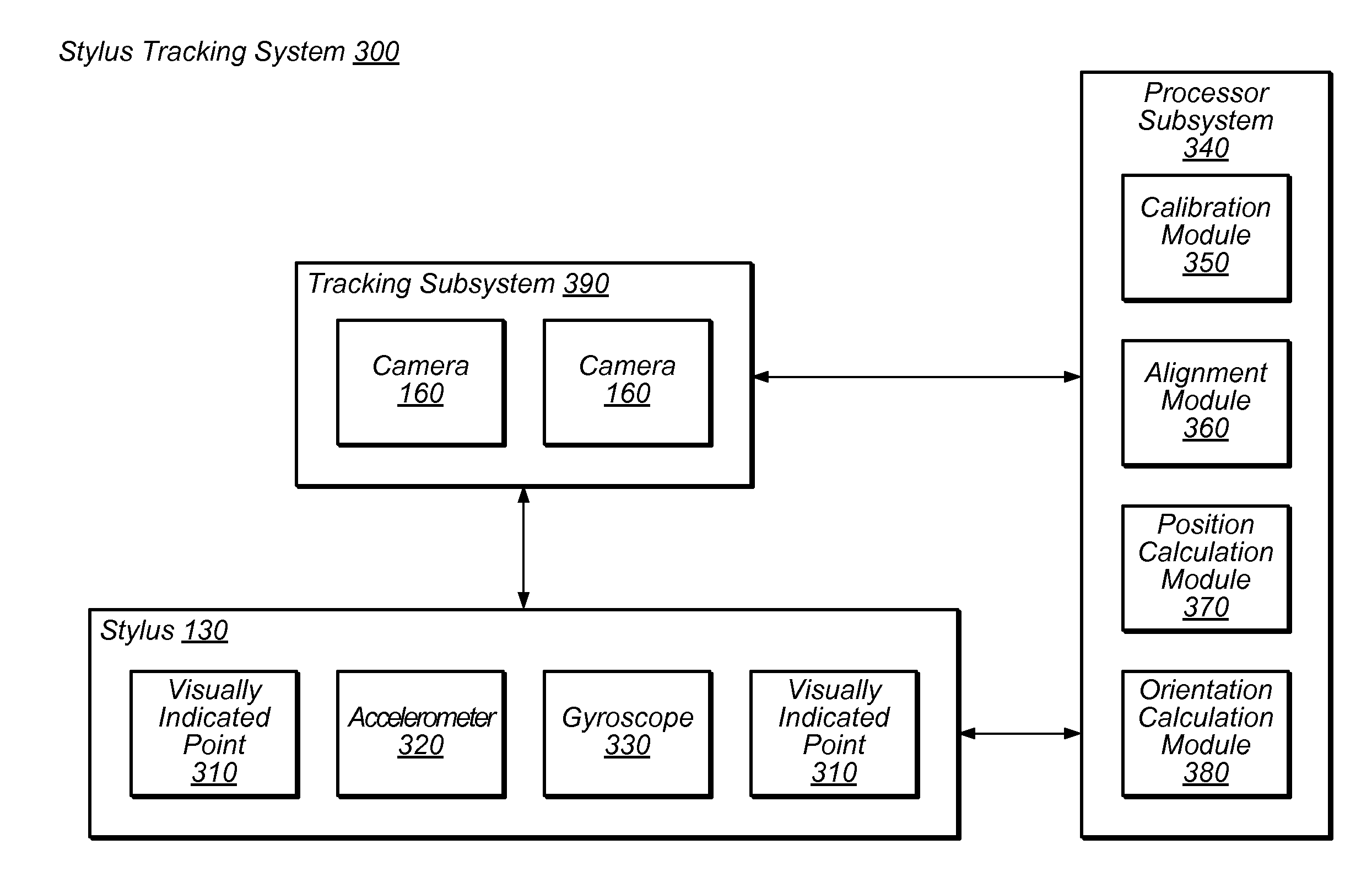
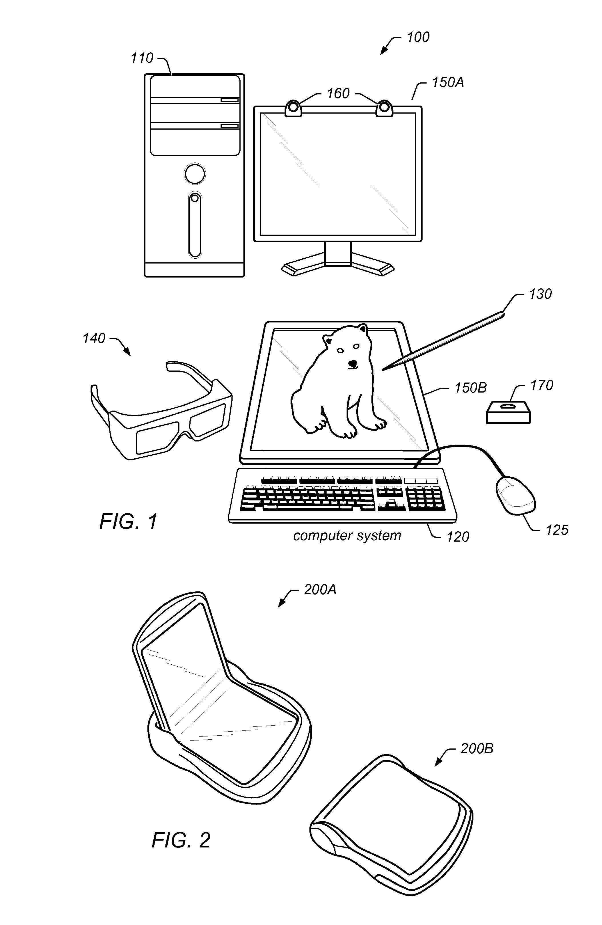
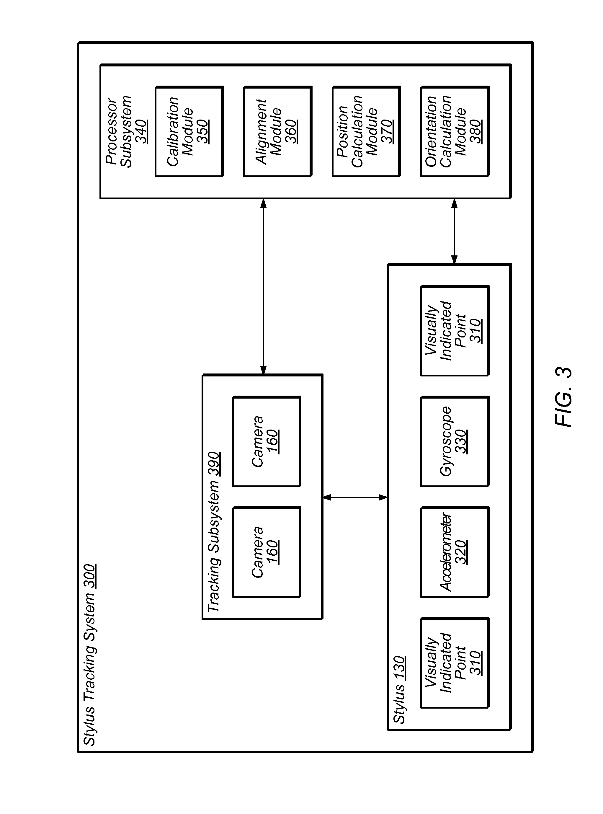
[0008]Embodiments relate to tracking objects presented within a three-dimensional (3D) scene. In one embodiment, a system includes a display configured to display the 3D scene. The system may include a user control device configured to manipulate objects within the 3D scene. The user control device (e.g., stylus) may include at least one visually indicated point. In one embodiment, at least one tracking sensor (e.g., camera) may be configured to capture the visually indicated point of the user control device. A processing subsystem may be configured to receive the captured visually indicated point from the tracking sensor and may also be configured to receive additional information from the user control device (e.g., measurement information from an accelerometer, gyroscope, magnetometer, etc.). The processing subsystem may be further configured to determine a position and orientation of the user control device based on the captured visually indicated point and the additional informa...


PUM


Abstract

Tracking objects presented within a stereo three-dimensional (3D) scene. The user control device may include one or more visually indicated points for at least one tracking sensor to track. The user control device may also include other position determining devices, for example, an accelerometer and / or gyroscope. Precise 3D coordinates of the stylus may be determined based on location information from the tracking sensor(s) and additional information from the other position determining devices. A stereo 3D scene may be updated to reflect the determined coordinates

Description

PRIORITY INFORMATION[0001]This application claims benefit of priority of U.S. Provisional Application Ser. No. 61 / 426,448 entitled “Three-Dimensional Tracking of Objects in a 3-D Scene” by David Chavez, Milind Paranjpe, Jerry Tu, and Michael Cheponis, filed Dec. 22, 2010, the content of which is incorporated by reference herein in its entirety as though fully and completely set forth herein.INCORPORATION BY REFERENCE[0002]The following references are hereby incorporated by reference in their entirety as though fully and completely set forth herein:[0003]U.S. patent application Ser. No. 11 / 098,681 (U.S. Patent Publication No. 2005 / 0219694), titled “Horizontal Perspective Display”, filed on Apr. 4, 2005.[0004]U.S. patent application Ser. No. 11 / 141,649 (U.S. Patent Publication No. 2005 / 0264858), titled “Multi-plane Horizontal Perspective Display”, filed on May 31, 2005.[0005]U.S. patent application Ser. No. 17 / 797,958, titled “Presenting a View within a Three Dimensional Scene”, filed...

Claims


Application Information

Patent Timeline
Patent Type & Authority Applications(United States)
IPC IPC(8): G06T15/00
CPCG06F3/012G06F3/013G06F3/0308G06F3/038G06F3/03545H04N13/0011H04N13/0468G06F3/0346G06F3/04815G06F3/04812H04N13/111H04N13/366G06F3/046
Inventor CHAVEZ, DAVID A.PARANJPE, MILINDTU, JEROME C.
Owner INFINITE Z
Why Eureka
Try Eureka