System to identify a user of television services by using biometrics

a biometric and television service technology, applied in television systems, analogue secracy/subscription systems, broadcast information monitoring, etc., can solve the problems of insufficient maturity of auto-stereoscopic and holographic displays

Inactive Publication Date: 2012-06-28
NAGRAVISION SA
View PDF0 Cites 41 Cited by
  • Summary
  • Abstract
  • Description
  • Claims
  • Application Information

AI Technical Summary

Benefits of technology

[0010]The circumference of a head is a simple biometric which fulfils the uniqueness requirement when considering a household with a limited number of persons. Typical

Problems solved by technology

Due to technical obstacles, auto-stereoscopic and holographic displays are not mature to be deployed.
Typically, in a household the head c

Method used


Image

  • System to identify a user of television services by using biometrics
  • System to identify a user of television services by using biometrics
  • System to identify a user of television services by using biometrics

Examples


first embodiment

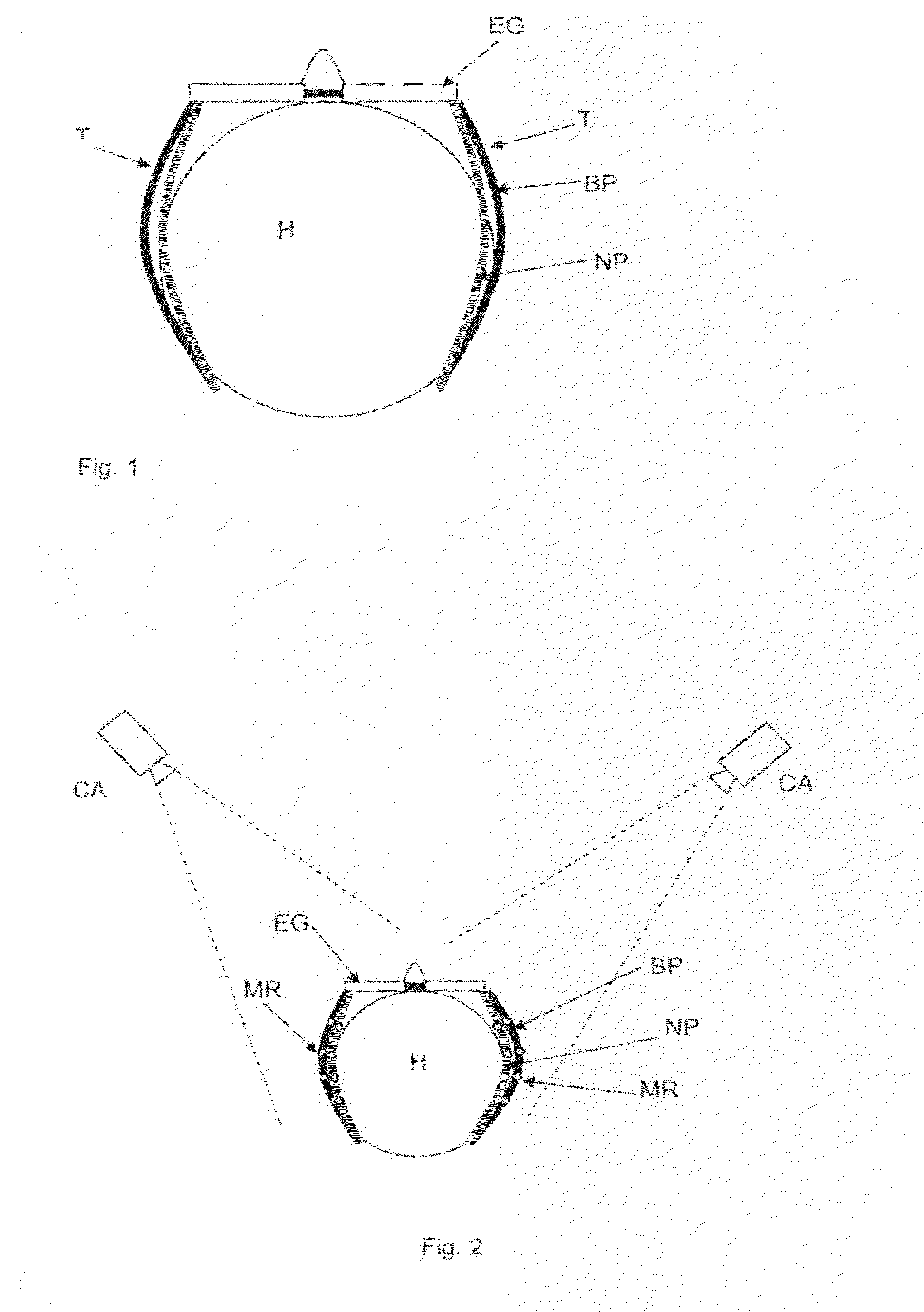
[0017]In the present invention a bend sensor BS may be integrated in the temples T of eyeglasses EG to measure a portion of the head H circumference. The temples T are curved to take on the exact shape of a portion of the circumference of the user's head H. The sensor BS produces a measurement value varying proportionally to the amount of the deflection of the temples T.

[0018]There are three most common types of bend sensors BS, cf. [5]:

a) Conductive ink-based sensor which electrical resistance changes depending on the amount of deflection on the bend sensor. These types of bend sensors are passive resistive devices typically fabricated by laying a strip of resistive ink on a flexible plastic substrate, shaped as a thin, flexible stripe in lengths between 1″ and 5″. At rest (when laid flat), the bend sensor is characterized by an intrinsic resistance. As the sensor is bent, the resistive materials inside it are pulled further apart. Fewer adjacent resistive particles come into conta...

second embodiment

[0023] the circumference of a head H is measured by using optical sensors OS as bend sensors BS similar to motion capture systems.

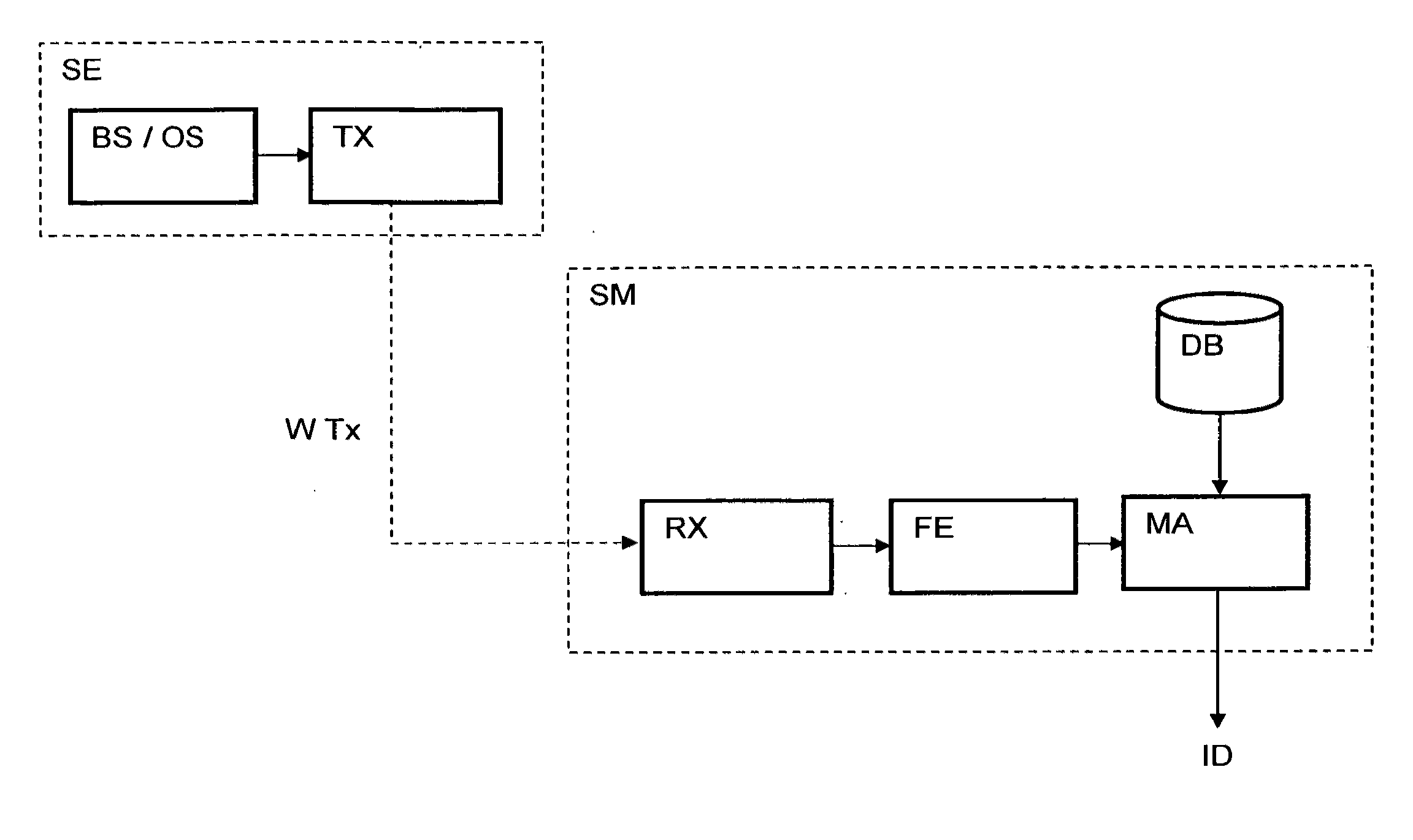
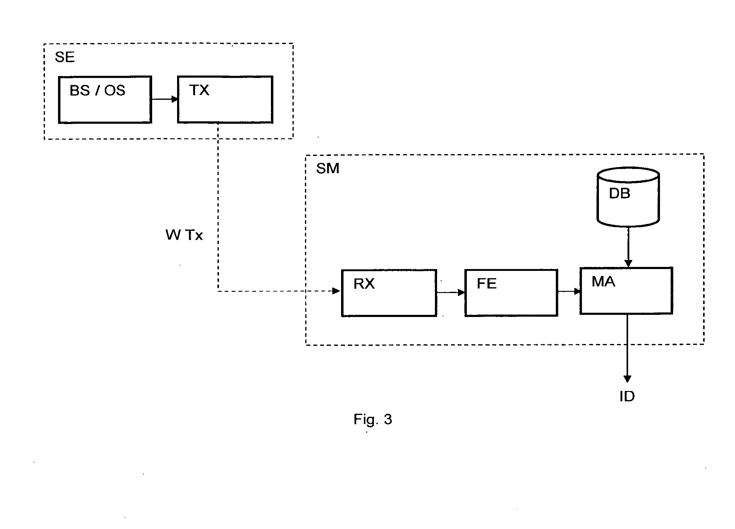
[0024]Light reflective markers MR are attached to the flexible temples T of the eyeglasses EG and aligned preferably at regular intervals along the length of the temple T. When the eyeglasses EG are worn, the temples T are bent to fit the shape of a portion of the circumference of the viewer's head H. In this way the positions of the markers change accordingly (see FIG. 2). At least one camera CA is arranged near the location of the user to acquire the biometrics by measuring the value of the deflection of the temples T through position variations of the markers MR between a neutral position NP and a bend position BP determined by the head circumference. The neutral position NP is defined by the position of the markers MR when the eyeglasses EG are put off from the user's head H. In this embodiment, the measurements values are transmitted wirelessly WTx t...


PUM


Abstract

A system to identify a user in relation with television services comprising eyeglasses worn by said user, said eyeglasses having a pair of flexible temples taking on the shape of a portion of the circumference of the user's head, a television receiver device comprising a server module communicating wirelessly with sensors arranged on the eyeglasses. The system is characterized in that each of the flexible temples of the eyeglasses incorporates at least one sensor configured for measuring a value of deflection caused by the temple bending around a portion of the circumference of the user's head, said value being unique for each user is transmitted as biometric to the server module configured for determining the identity of the user according to the measured value of the portion of the user's head circumference.

Description

CROSS REFERENCE TO RELATED APPLICATIONS[0001]This application claims priority under 35 U.S.C. Section 119 to U.S. Provisional Application No. 61 / 426,546, entitled “A system to measure the head circumference as a biometric” filed Dec. 23, 2010, and to European Patent Application EP 11180961.2 entitled “A system to identify a user of television services by using biometrics” filed Sep. 12, 2011, the contents of which are hereby incorporated by reference herein.FIELD OF THE INVENTION[0002]This invention relates to user identification for personalized services, targeted advertising, and audience measurement in the field of media broadcasting or Internet Protocol media streaming such as television program content.TECHNICAL BACKGROUND[0003]Several methods and devices for user identification based on biometrics are available to filter or to authorize users accessing value added services. For example:[0004]EP1593964A1 discloses a biological sensor device including a sensor-mounting element w...

Claims


Application Information

Patent Timeline
IPC IPC(8): H04N21/4415
CPCH04H60/45H04N13/0429H04N21/44218H04N21/4415H04N21/42201H04N13/332
Inventor ABDELJAOUED, YOUSRI
Owner NAGRAVISION SA
Why Eureka
Try Eureka