
Television receiver including an integrated band selection filter

a filter and receiver technology, applied in the field of television signal receivers, can solve the problems of lack of high q value integrated inductors, inability to adapt to tuning applications of most integrated inductors available today, and the integration of band pass filters, etc., to achieve high q values, low series resistance, and large inductance

Inactive Publication Date: 2006-02-23
CF CRESPE LLC
View PDF12 Cites 93 Cited by
  • Summary
  • Abstract
  • Description
  • Claims
  • Application Information

AI Technical Summary

Benefits of technology

[0052] The spiral-in and spiral-out nature of the metal spirals forming the integrated inductor of the present invention has particular advantages in that metal line cross-over is completely avoided. In inductor 700 of the present invention, the two terminals of the inductor is formed at the perimeter of the metal spirals thus no metal line crossing over the metal spirals is required to form the two inductor terminals.

Problems solved by technology

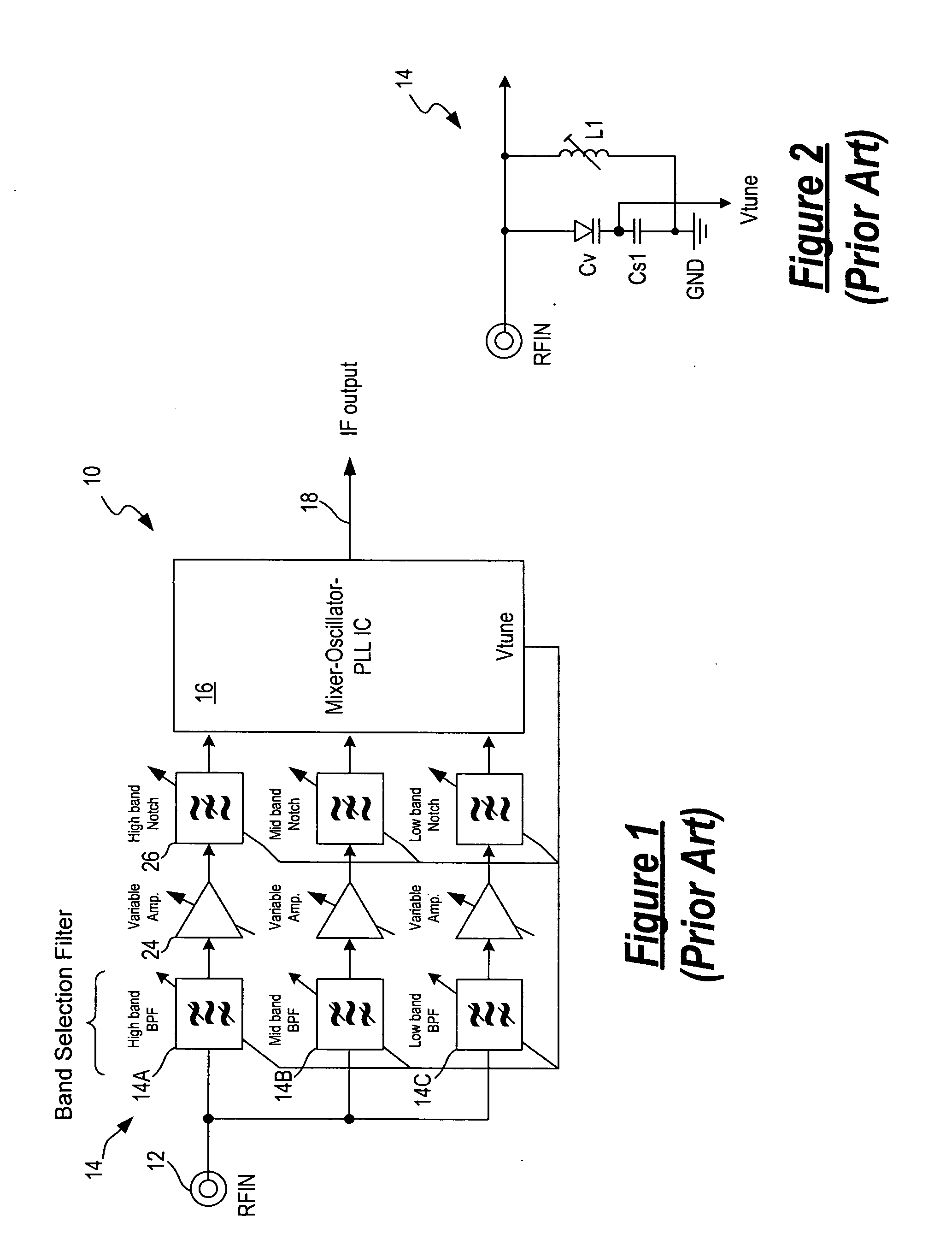
The primary barrier to the integration of the band pass filter is the lack of high Q values integrated inductors.
Thus, most integrated inductors available today are not suitable for tuning applications as those integrated inductors only work in a very narrow bandwidth and tuning requires a large bandwidth of operation.
For example, while it is relatively easy to achieve high Q values at 800 MHz, it is extremely difficult to achieve meaningful Q values at 200 MHz using conventional integrated inductor technologies.
To make adequate integrated inductor for use in tuning purposes, the integrated inductor becomes too large for practical implementation.
Another barrier to the complete integration of the tuner module of the TV receiver is the notch filter used for image rejection.
Similar to the reasons that make integration of a band pass filter difficult, it is difficult to make notch filters in an integrated circuit because of the lack of high Q values integrated inductors.
Thus, it is often not practical to integrate the notch filter into an integrated circuit.
This approach is undesirable because the complete front-end, including the amplifiers and mixers, must be able to deal with the total power of the entire spectrum therefore requiring a large power consumption to guarantee a sufficient linearity.

Method used


Image

  • Television receiver including an integrated band selection filter
  • Television receiver including an integrated band selection filter
  • Television receiver including an integrated band selection filter

Examples


Embodiment Construction

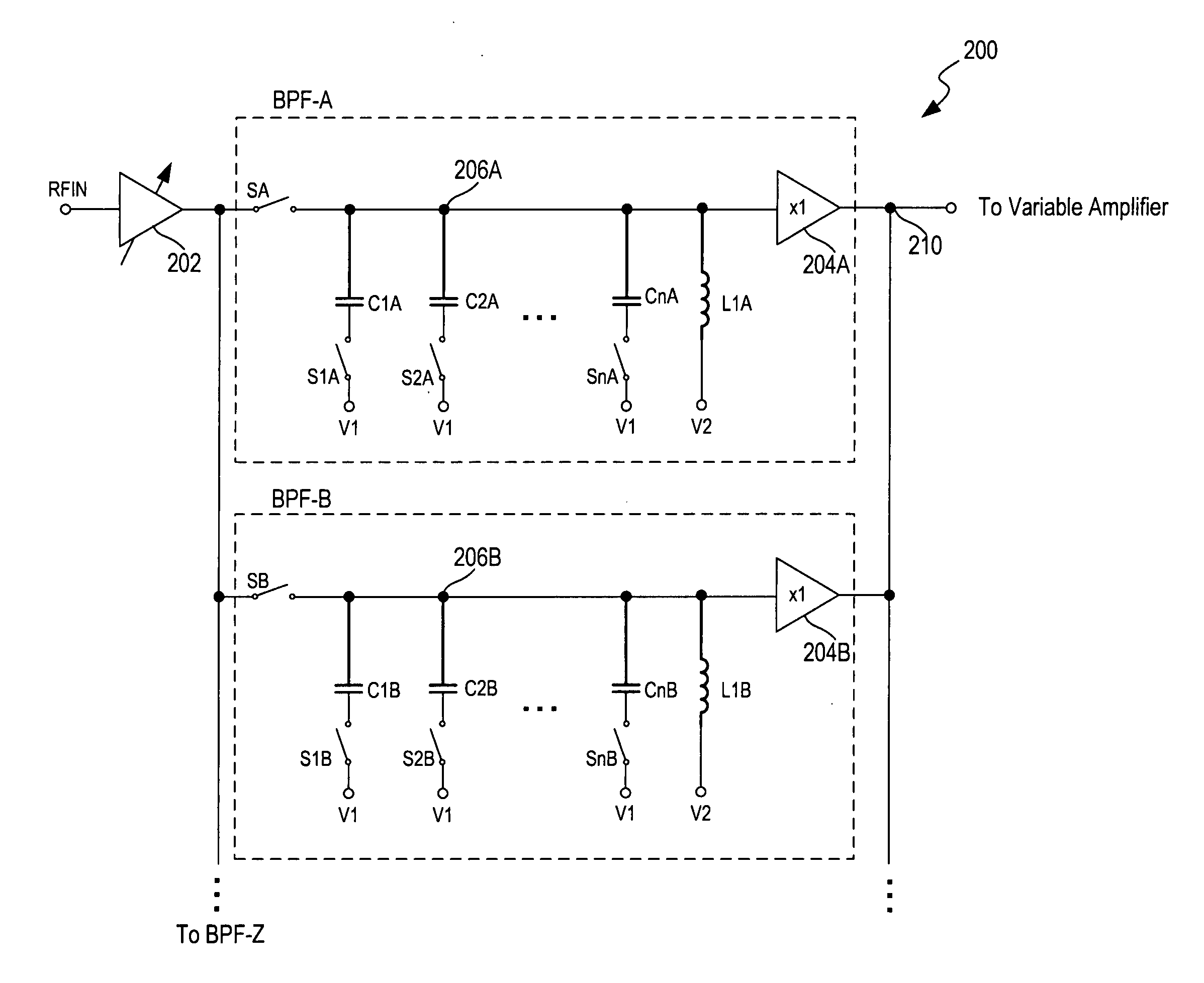
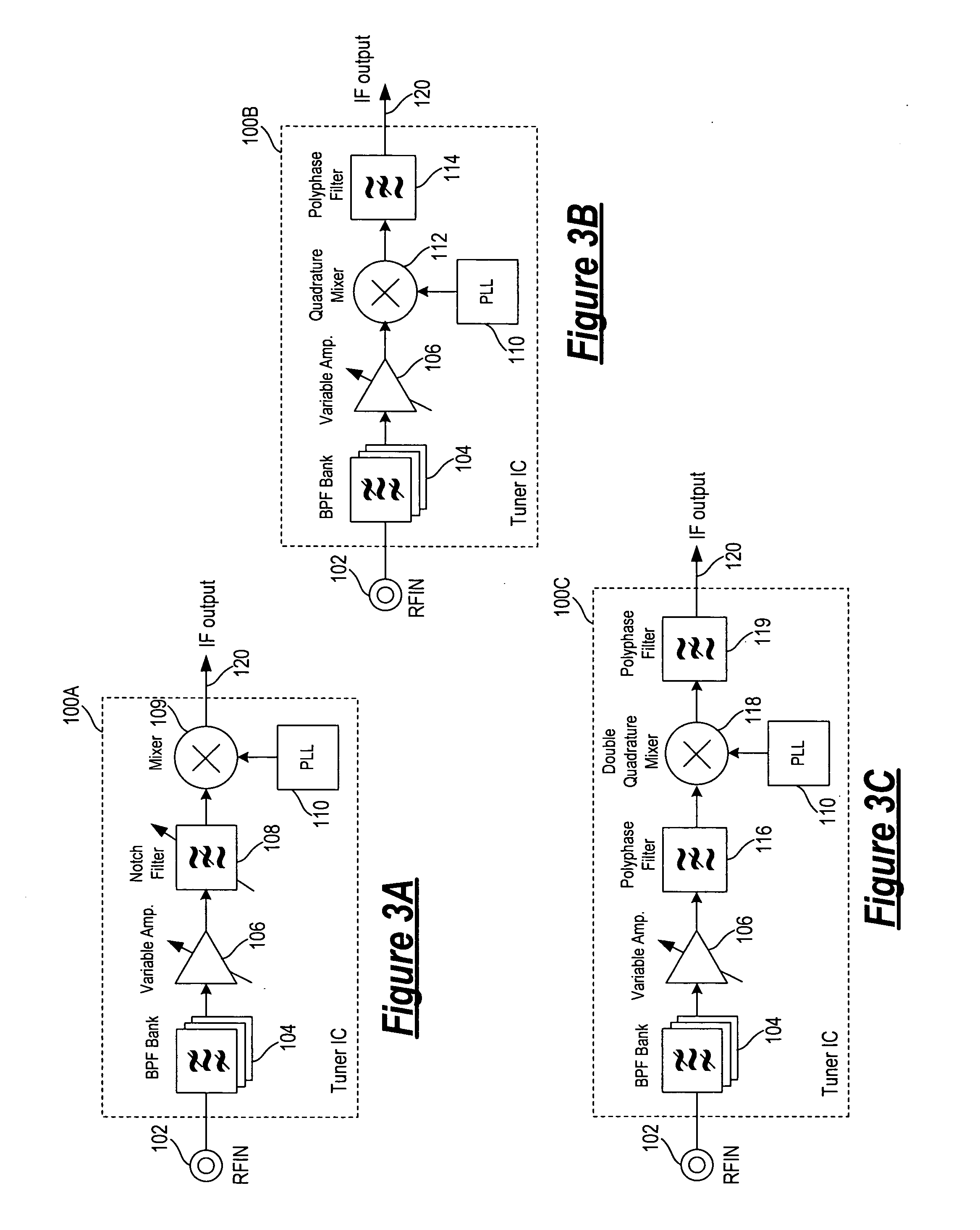
[0027] In accordance with the principles of the present invention, a television receiver includes a tuner circuit incorporating an integrated band selection filter. In one embodiment, the integrated band selection filter is implemented using a bank of integrated band pass filters incorporating integrated inductors where the integrated inductors are formed as single-spiral or multi-spiral integrated planar inductors. By using the integrated planar spiral inductor structure, an integrated inductor having sufficiently large inductance value (e.g., greater than 100 nH) with low series resistance can be formed while maintaining practical dimensions. As a result, integrated inductors of high Q values at low frequency can be achieved using processing steps and features that are common to conventional fabrication processes. By using the integrated band selection filter of the present invention, an integrated television receiver can be realized where the tuner circuit, including the band sel...


PUM


Abstract

A tuner circuit includes a band selection filter coupled to receive an input RF signal and provide a band selected output signal where the band selection filter includes a bank of band pass filters. Each band pass filter includes an inductor and a variable capacitor forming an LC resonator where the inductor is an integrated planar spiral inductor. The tuner circuit further includes a frequency conversion circuit coupled to receive an input signal corresponding to the band selected output signal and provide a frequency converted output signal having a predetermined frequency. The integrated planar spiral inductor can be formed using a single metal spiral or multiple metal spirals. In a multi-spiral structure, a first metal spiral having an inward spiral pattern and a second metal spiral having an outward spiral pattern to form an inductor with large inductance, low series resistance and high Q values, even at low frequency.

Description

FIELD OF THE INVENTION [0001] The invention relates to a television signal receiver, and, in particular, to a television signal receiver including an integrated band selection filter. DESCRIPTION OF THE RELATED ART [0002] A television (TV) or video recorder includes a television signal receiver (or television receiver) to receive terrestrial broadcast, cable television or satellite broadcast television signals and to process the television signals into the appropriate video signals for display or for recording. Television signals are transmitted in analog or digital formats and in accordance with a variety of standards. [0003] The operation of a television receiver includes two main components. First, the receiver receives the incoming television signal in radio frequency (RF) and converts the incoming RF signal to an intermediate frequency (IF) signal. Then, the receiver converts the IF signal to a video baseband signal and an audio baseband signal. The baseband signals are coupled...

Claims


Application Information

Patent Timeline
IPC IPC(8): H04B7/00H03J5/24
CPCH03J2200/10H03J5/244
Inventor PORRET, ALAIN-SERGEFAVRAT, PIERREPYTHON, DOMINIQUEMARGAIRAZ, DIDIER
Owner CF CRESPE LLC
Learn More