Power source circuit

Active Publication Date: 2013-05-09
CANON KK
View PDF4 Cites 4 Cited by
  • Summary
  • Abstract
  • Description
  • Claims
  • Application Information

AI Technical Summary

Benefits of technology

[0007]However, to prevent a circuit element from troubles, the switching power source includes an excess current protection element (e.g., fuse) at an input side of the Y capacitor

Problems solved by technology

However, in the power source circuit adopting the switching method, a switching noise having a high frequenc

Method used


Image

  • Power source circuit
  • Power source circuit
  • Power source circuit

Examples


example 1

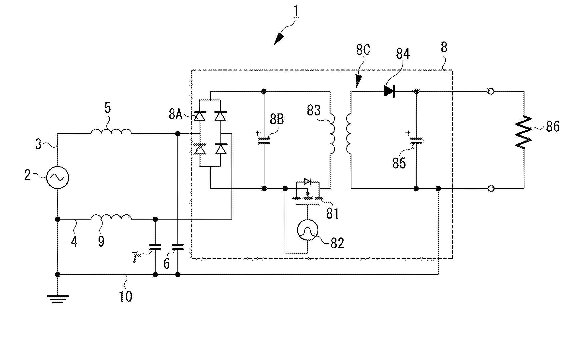
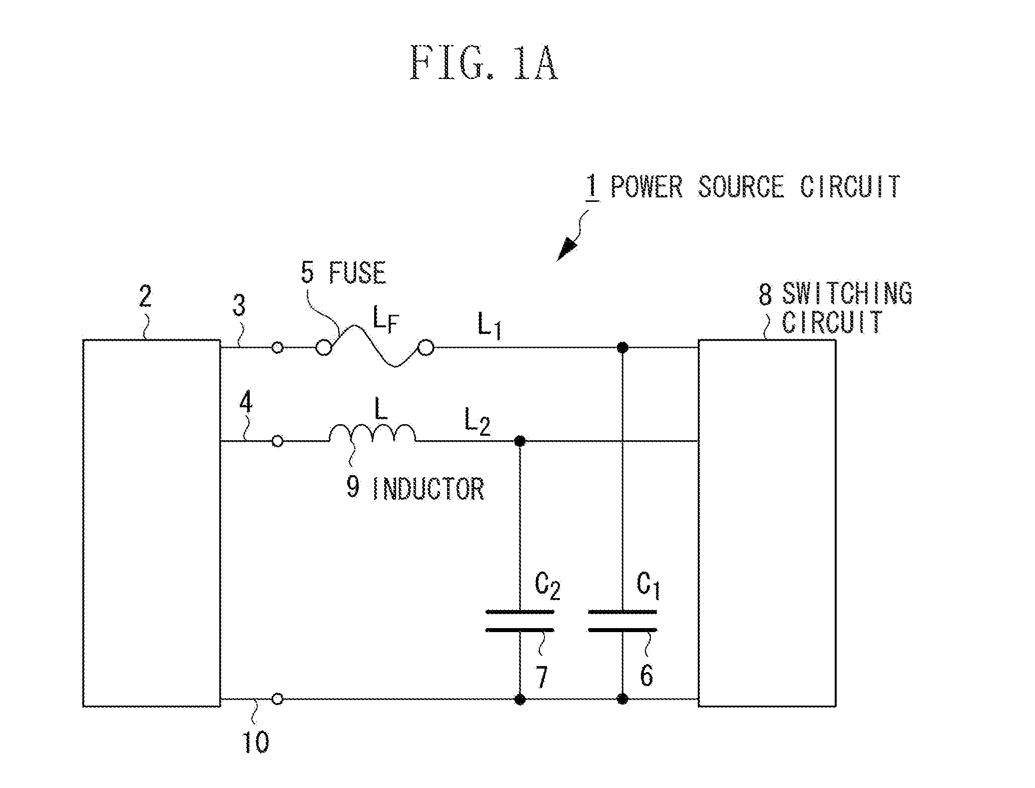
[0024]FIG. 1 illustrates a schematic configuration of a power source circuit according to a first exemplary embodiment of the present invention. FIG. 1A is a schematic electric circuit diagram of the power source circuit. In FIG. 1A, a power source circuit 1 includes a pair of supply lines 3 and 4 connected to an alternating power source 2, a switching circuit 8 as a power conversion circuit for converting the alternating voltage from the alternating power source 2 into a direct current voltage via the pair of supply lines 3 and 4. The alternating power source 2 is, for example, a power source for commercial use.

[0025]Further, the power source circuit 1 includes a fuse 5 as an excess current protection element provided for, of the pair of supply lines 3 and 4, one supply line 3 that is a positive voltage. This fuse 5 is, for example, a tube fuse. The fuse 5 has a higher inductance value than that of a wiring constituting the supply lines 3 and 4.

[0026]Furthermore, the power source c...

example 2

[0050]Next the power source circuit according to a second exemplary embodiment of the present invention will be described in detail. FIGS. 5A and 5B illustrate schematic configurations of the power source circuit according to the second exemplary embodiment of the present invention. FIG. 5A is a schematic electric circuit diagram of the power source circuit.

[0051]In FIG. 5A, the power source circuit 1A includes the pair of supply lines 3 and 4 connected to the alternating power source 2, a switching circuit 8 as a power conversion circuit for converting the alternating voltage from the alternating power source 2 via the pair of the supply lines 3 and 4 into the direct current voltage. The alternating power source 2 is, for example, the power source in commercial use.

[0052]Further, the power source circuit 1A includes the fuse 5 as the excess current protection element provided for, of the pair of supply lines 3 and 4, one supply line 3 having the positive voltage. The fuse5 is, for ...


PUM


Abstract

In a power source circuit including a switching circuit 8 as a power conversion circuit for converting by a switching operation at least one of a frequency and a voltage of an alternating voltage from an alternating power source 2 via a pair of supply lines 3 and 4, one supply line 3 includes a fuse 5 as an excess current protection element, and between a ground line 10 and one supply line 3, a first line bypass capacitor 6 is connected. Between the ground line 10 and another supply line 4, a second line bypass capacitor 7 is connected, and another supply line 4 includes an inductor 9. With this configuration, an unbalanced state of the circuit due to the excess current protection element is reduced so as to restrain the common mode noise.

Description

TECHNICAL FIELD[0001]The present invention relates to a power source circuit that restrains a high frequency noise generated by a switching operation.BACKGROUND ART[0002]A conventional electronic device includes a power conversion circuit to convert a frequency or a voltage of an arbitrary input power source into frequencies or voltages for various devices in the electronic device. Particularly, a switching method is widely used to make the power conversion circuit compact and efficient. However, in the power source circuit adopting the switching method, a switching noise having a high frequency is generated by the switching operation, thereby causing a terminal noise or an electromagnetic wave noise.[0003]As a noise filter for reducing such an electromagnetic noise, Japanese Patent Application Laid-Open No. 2008-182784 discusses a line bypass capacitor (hereinafter, referred to as a “Y capacitor”). FIG. 9 is an example of a filter circuit diagram used for a conventional switching p...

Claims


Application Information

Patent Timeline
IPC IPC(8): H02M1/32
CPCH02M1/12H02M1/32H02M7/217H02M2001/123H02M1/123
Inventor IDE, TAKESHISEKIJIMA, DAISHIRO
Owner CANON KK
Why Eureka
Try Eureka