Modeled object updating

a technology of modeled objects and objects, applied in the field of computer programs and systems, can solve the problems of inability to display complex parts, inability to balance the said history structure, and difficulty for users to display complex parts

Active Publication Date: 2012-07-05
DASSAULT SYSTEMES
View PDF4 Cites 19 Cited by
  • Summary
  • Abstract
  • Description
  • Claims
  • Application Information

AI Technical Summary

Problems solved by technology

The B-rep is generally saved together with the history because it is not possible to display complex parts only from the history data.
When the history structure is controlled by the user, it is an additional difficulty for the user to balance the said history structure while designing a complex part.
An inexperienced designer cannot perform this double task.
The second drawback is that many operations are recomputed only because they are on the path (from the modified leaf node down to the root node) while they do not influence the resulting solid.
Deciding whether an operation is meaningful or not during the update is a difficult question.
As a consequence, the update is slow.
This behavior is undesirable from the designer's point of view.
As a consequence, the update is slow.
A very simple modification would require the same amount of computation than a complex modification, which is not optimal from the designer's point of view.
As a consequence, the update is slow.
Firstly, it does not take into account non Boolean operations such as draft angle, round, fillet, shell and thickness which are very popular in mechanical design.
This restriction to pure Boolean operations is a major drawback in mechanical design and in solid modeling in general because a real life part always features some non Boolean characteristics (round, fillet, shell etc.).
Secondly, even in the pure Boolean case, there are examples when this technology is not efficient.
As a consequence, the update is slow, all the more when there are non-Boolean operations in the history.
B-rep modeling does not save the history of the part.
The first drawback is a lack of semantic.
The design intent expressed through the history is lost, and reusing predefined models is not possible.
Secondly, not all topological and geometrical changes are possible through B-rep modeling.
B-rep modeling does not guarantee this property.
However, as no information on the operations which the object has undergone is kept, a subsequent modification is actually difficult for the user.
Furthermore, B-rep modeling has geometrical and topological restrictions which lead designers to often prefer history based modeling.
Kripac's algorithm is not compatible with intermediate results saving as described earlier because the history tree is rebalanced for each modification.
Beyond the computer time required for algebraic manipulations, the geometrical and topological complexity of the constant solids involved in the reduced history tree is comparable to the complexity of the whole solid.
Given that the constant solids are computed from scratch, the consequence is that the reduced history tree step is almost as costly as computing the whole solid from scratch.
As a consequence, before the real time capability is available, the designer must wait during a time period that is generally too long.
Furthermore, there exists a failure risk because algebraic manipulations may duplicate primitives in the reduced history tree, which causes tangent or locally identical surfaces situations.
It is well known that these situations are handled with enormous difficulty by geometrical modelers.
Furthermore, the integrity of the data model is not guaranteed because the computation performed by the system to provide the modified solid is totally different from the computation performed to create the solid from the modified primitives through the initial history.
Drawbacks are thus a costly preprocessing and a potential geometrical fragility.
As a consequence, the update is slow.
The first drawback is that in some cases, features are recomputed despite they do not change the resulting solid.
The second drawback is that the computing path followed by the system to update the solid is totally different from the computing path to generate the modified solid from scratch.

Method used


Image

  • Modeled object updating
  • Modeled object updating
  • Modeled object updating

Examples


Embodiment Construction

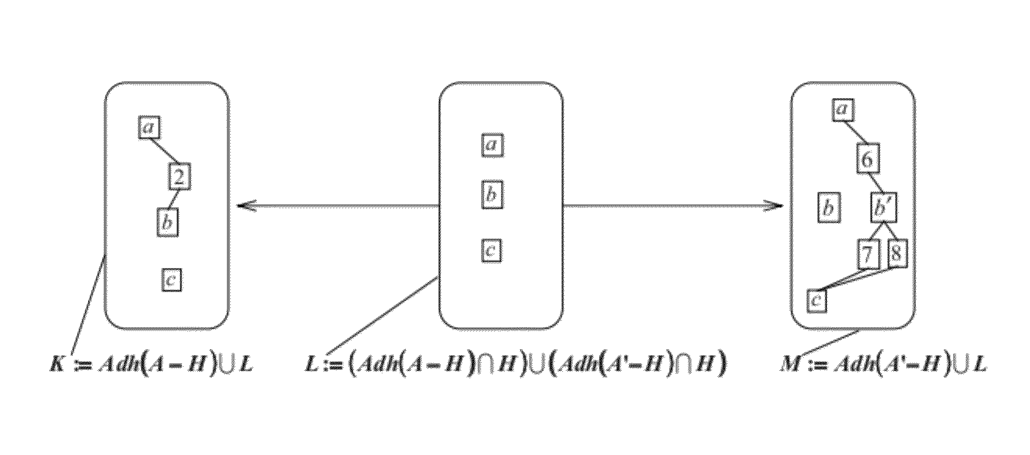
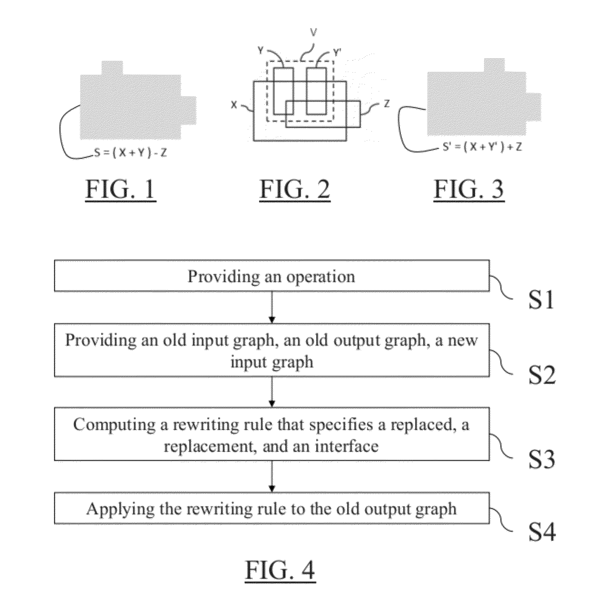
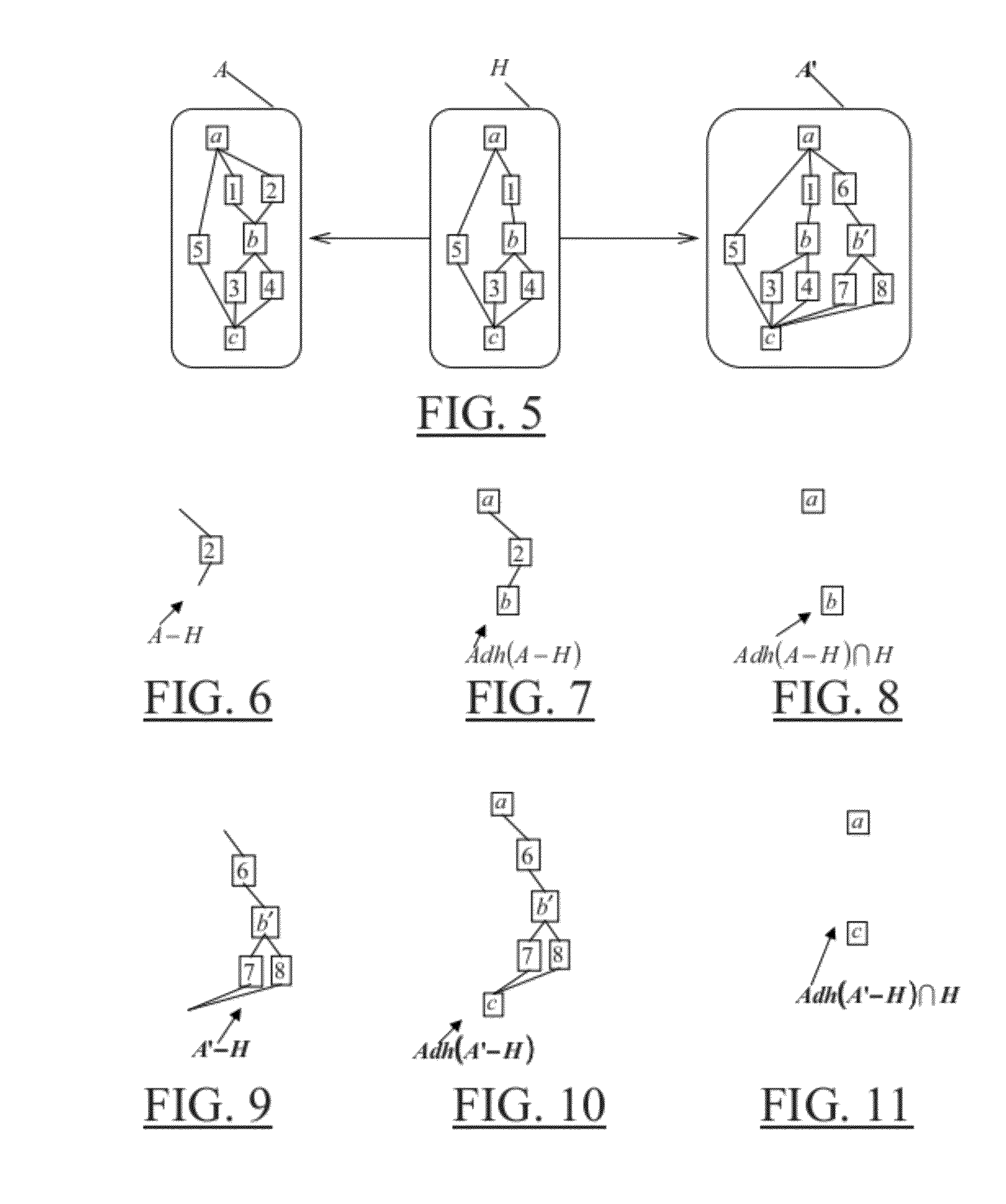
[0064]With reference to the flowchart of FIG. 4, it is proposed a method for updating a modeled object. The method comprises providing (S1) an operation. The method also comprises providing (S2) an old input graph of the operation, an old output graph corresponding to an application of the operation to the old input graph, a new input graph of the operation. The method further comprises computing (S3) a rewriting rule that specifies a “replaced”. The replaced is a part of the old input graph to be replaced. The rewriting rule also specifies a “replacement”. The replacement is a part of the new input graph to replace the replaced. The rewriting rule further specifies an “interface”. The interface is a part common to the replaced, the replacement and the old output graph. The method then comprises applying (S4) the rewriting rule to the old output graph. Such a method improves the update of a modeled object.

[0065]A modeled object is an object modeled by data allowing a computer manipu...


PUM


Abstract

It is provided a computer-implemented method for updating a modeled object. The method comprises providing an operation, an old input graph of the operation, an old output graph corresponding to an application of the operation to the old input graph, a new input graph of the operation. The method also comprises computing a rewriting rule that specifies a replaced which is a part of the old input graph to be replaced, a replacement which is a part of the new input graph to replace the replaced, an interface which is a part common to the replaced, the replacement and the old output graph. The method further comprises applying the rewriting rule to the old output graph. The method is an improvement to updating a modeled object.

Description

RELATED APPLICATION(S)[0001]This application claims priority under 35 U.S.C §119 or 365 to European Application No. 10306543.9, filed Dec. 30, 2010.[0002]The entire teachings of the above application(s) are incorporated herein by reference.FIELD OF THE INVENTION[0003]The invention relates to the field of computer programs and systems, and more specifically to a method, system and program for updating a modeled object.BACKGROUND[0004]Computer-aided techniques are known to include Computer-Aided Design or CAD, which relates to software solutions for authoring product design. Similarly, CAE is an acronym for Computer-Aided Engineering, e.g. it relates to software solutions for simulating the physical behavior of a future product. CAM stands for Computer-Aided Manufacturing and typically includes software solutions for defining manufacturing processes and operations.[0005]A number of systems and programs are offered on the market for the design of objects (or parts) or assemblies of obj...

Claims


Application Information

Patent Timeline
Patent Type & Authority Applications(United States)
IPC IPC(8): G06F17/10
CPCG06F17/50G06T17/10G06F2217/04G06T2219/2021G06T19/20G06F30/00G06F2111/02
Inventor RAMEAU, JEAN-FRANCOISHOUDOUIN, JEAN-MICHELJANVIER, JEAN-BAPTISTEMORAWSKA, JADWIGA MARIA
Owner DASSAULT SYSTEMES
Why Eureka
Try Eureka