

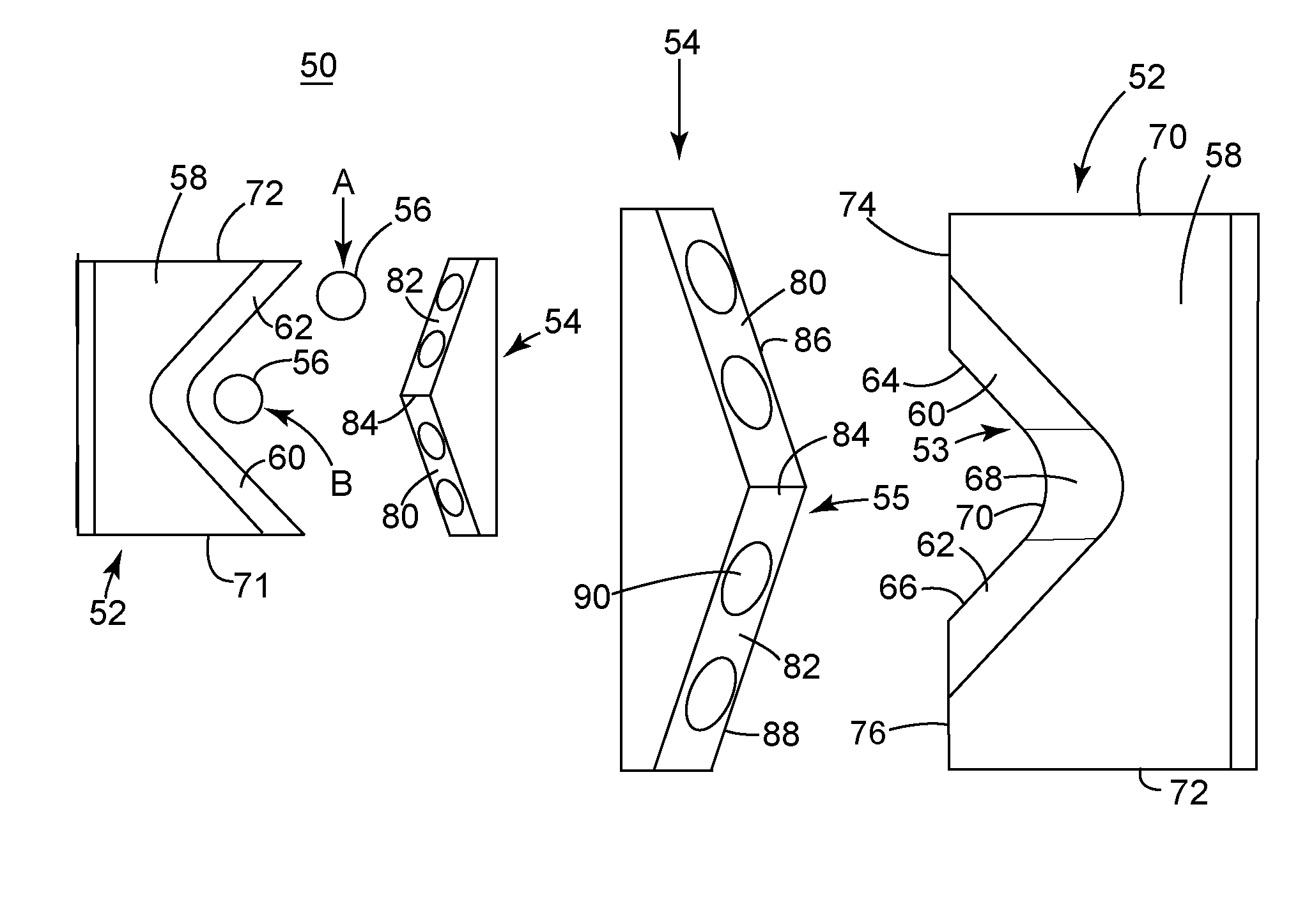
Shear Blade Geometry and Method
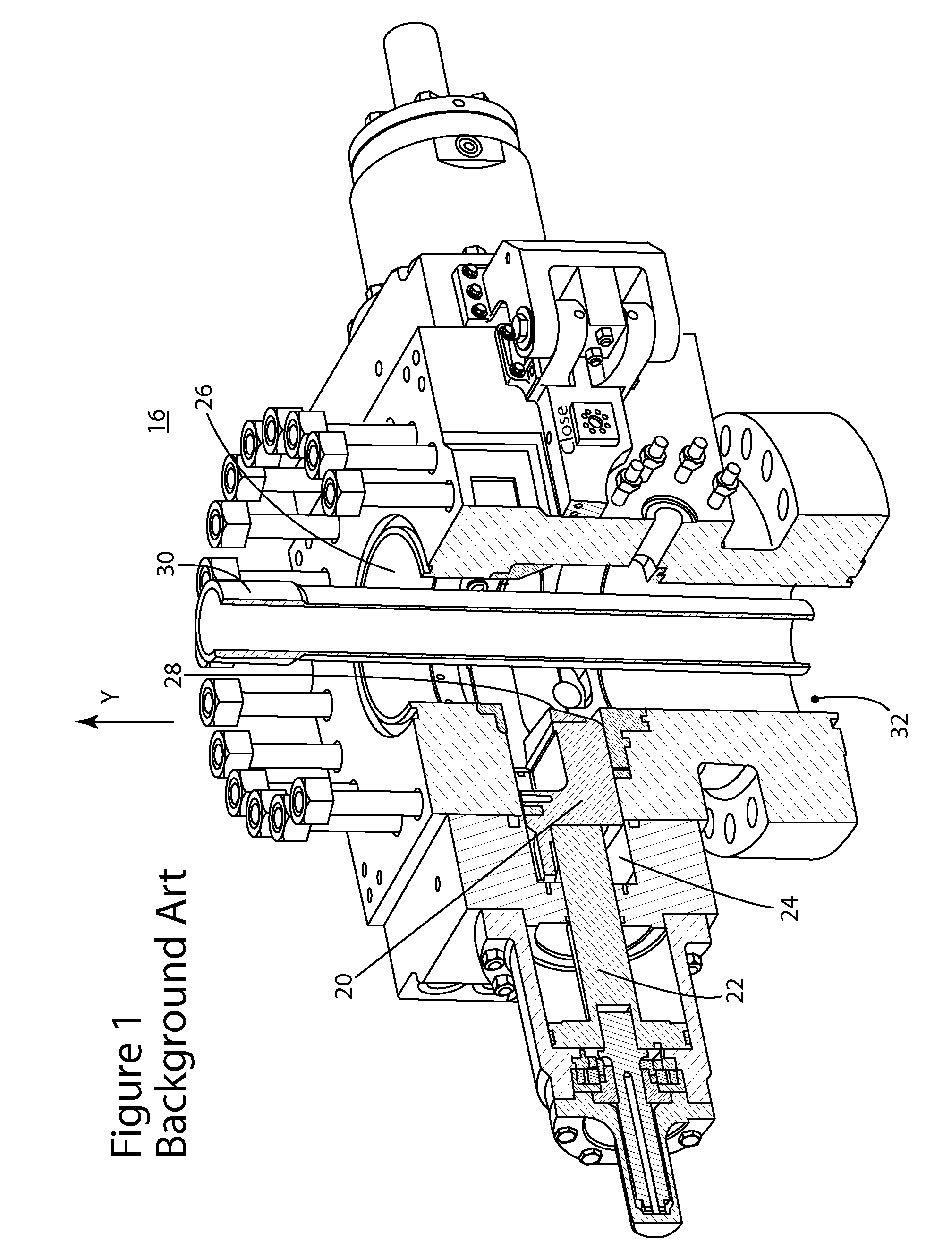
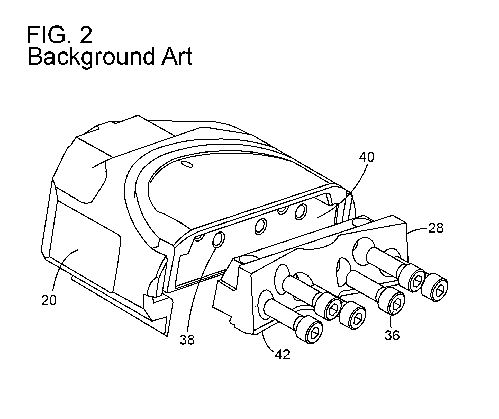
a technology of shear blades and geometry, applied in the direction of tube shearing machines, sealing/packing, borehole/well accessories, etc., can solve the problems of cutting edges that fail to shear the tubular, the well cannot be sealed, and the human life loss
- Summary
- Abstract
- Description
- Claims
- Application Information
AI Technical Summary
Benefits of technology
Problems solved by technology
Method used
Image

Examples
Embodiment Construction
[0027]The following description of the exemplary embodiments refers to the accompanying drawings. The same reference numbers in different drawings identify the same or similar elements. The following detailed description does not limit the invention. Instead, the scope of the invention is defined by the appended claims. The following embodiments are discussed, for simplicity, with regard to the terminology and structure of shear ram BOP systems. However, the embodiments to be discussed next are not limited to these systems, but may be applied to other systems that require cutting a tool.
[0028]Reference throughout the specification to “one embodiment” or “an embodiment” means that a particular feature, structure, or characteristic described in connection with an embodiment is included in at least one embodiment of the subject matter disclosed. Thus, the appearance of the phrases “in one embodiment” or “in an embodiment” in various places throughout the specification is not necessaril...
PUM
| Property | Measurement | Unit |
|---|---|---|
| Angle | aaaaa | aaaaa |
| Angle | aaaaa | aaaaa |
Abstract
Description
Claims
Application Information