Mobile Platform Structure Able to Vary Viewing Focal Length

a technology of mobile platforms and focal lengths, applied in the direction of machine supports, electric apparatus casings/cabinets/drawers, instruments, etc., can solve the problems of user's eyes being likely to fatigue, and no effective measure to solve the abovementioned problem

Inactive Publication Date: 2012-08-02
PAN TU CHENG
View PDF3 Cites 7 Cited by
  • Summary
  • Abstract
  • Description
  • Claims
  • Application Information

AI Technical Summary

Benefits of technology

[0005]Accordingly, the present invention proposes a mobile platform structure able to vary a viewing focal length, which comprises a mobile platform, a base, a slide rail, a tooth bar, a motor, a transmission gear, a control module, a signal cable, a telemeter, and a power cord. The mobile platform is movably coupled to the base via the slide rail and able to move back and forth. The mobile platform is equipped with the tooth bar and actuated to move by the motor and transmission gear arranged on the base. The control module controls the motor to move the platform at a specified timing by a specified distance according to the setting stored in the control module, whereby the viewing focal length of the user, who watches the display on the platform, can vary frequently lest the eyes fatigue. The telemeter is installed on the mobile platform and used to detect the distance between the user's face and the platform. If the user's face approaches the platform too much, the control module controls the motor to move the platform to have an appropriate distance to the user's face. The platform structure can be arranged on a desktop 12, integrated with a table, or installed on the baseplate of a display rack. As describe above, the present invention possesses utility, novelty and non-obviousness.

Problems solved by technology

When the user has watched a display or a notebook computer for a long time, or when the user watches the display at a distance too long or too short, the user's eyes are likely to fatigue.
However, there is none effective measure to solve the abovementioned problem.

Method used


Image

  • Mobile Platform Structure Able to Vary Viewing Focal Length
  • Mobile Platform Structure Able to Vary Viewing Focal Length
  • Mobile Platform Structure Able to Vary Viewing Focal Length

Examples


Embodiment Construction

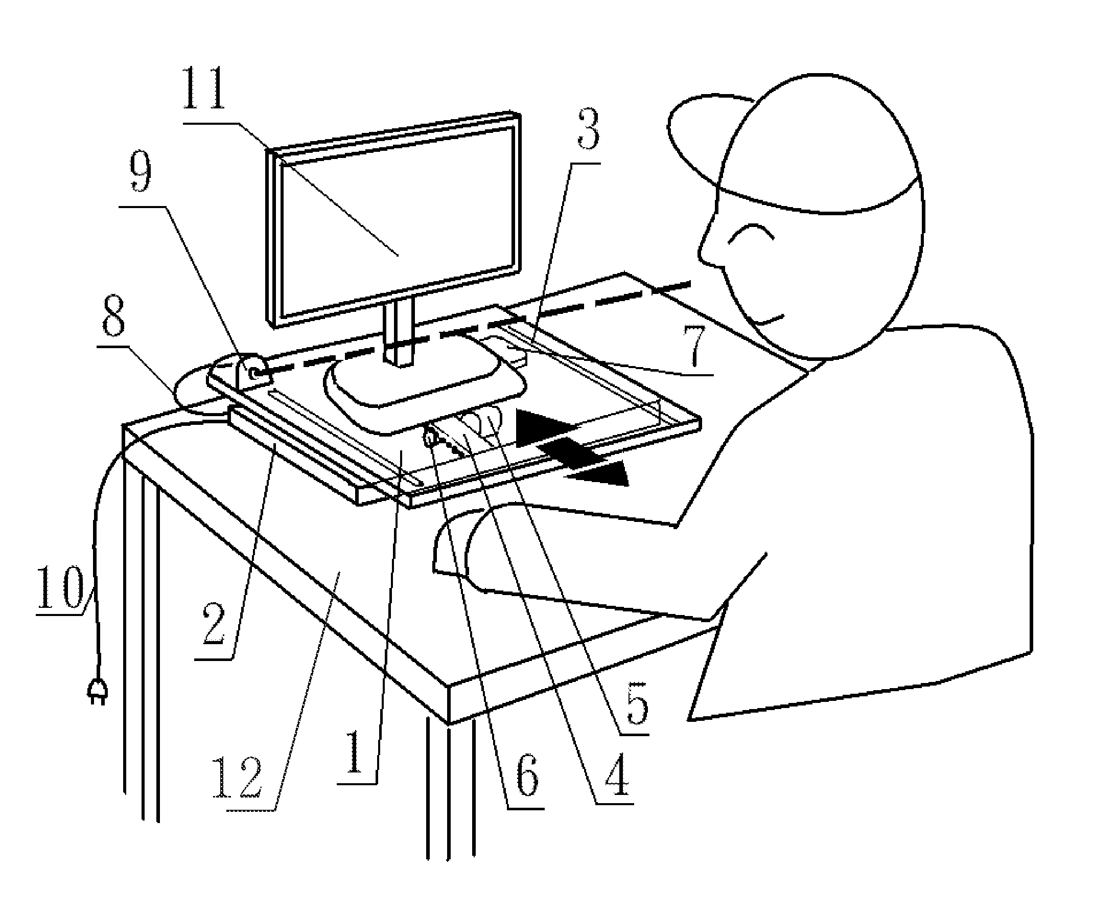
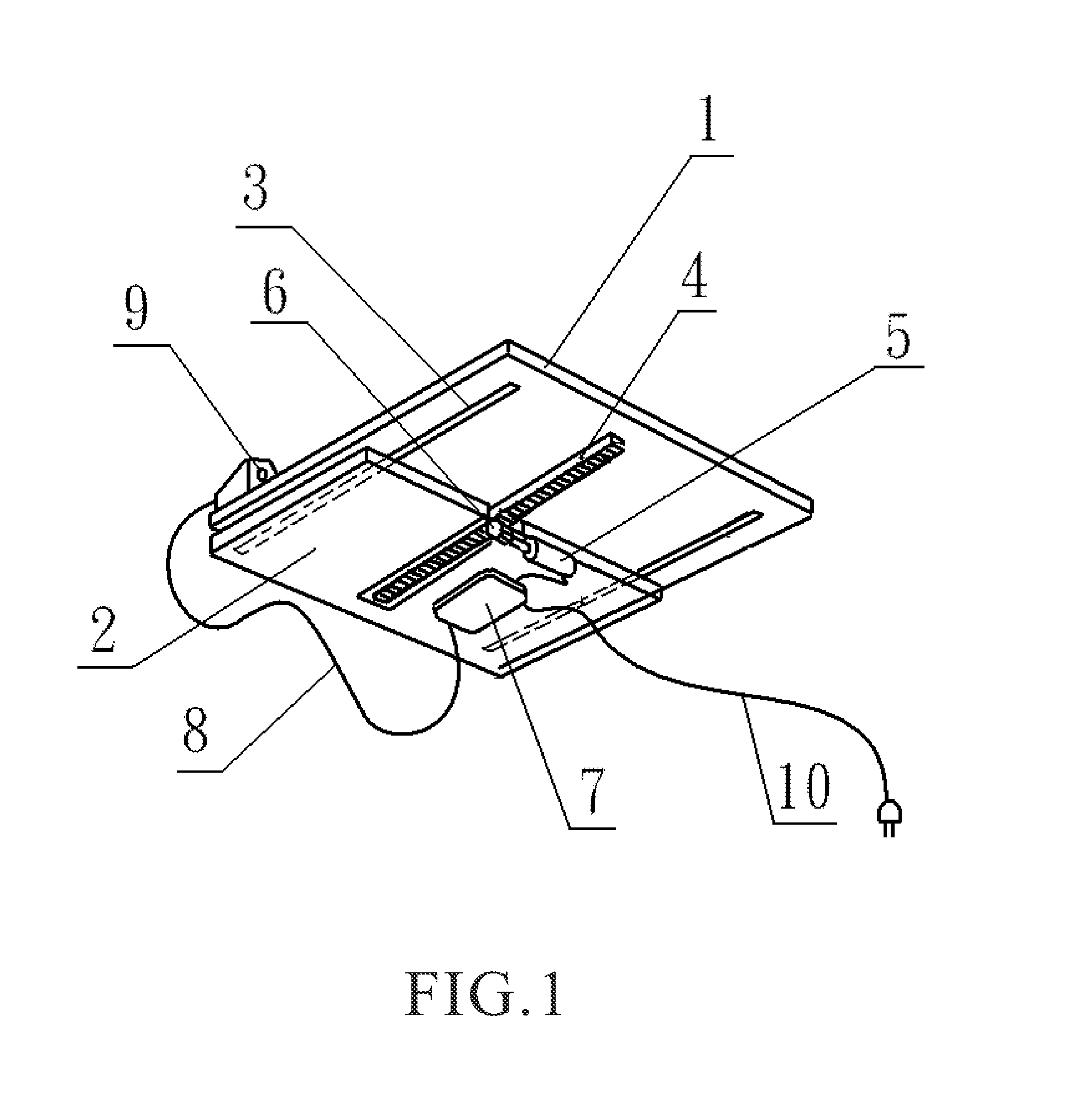
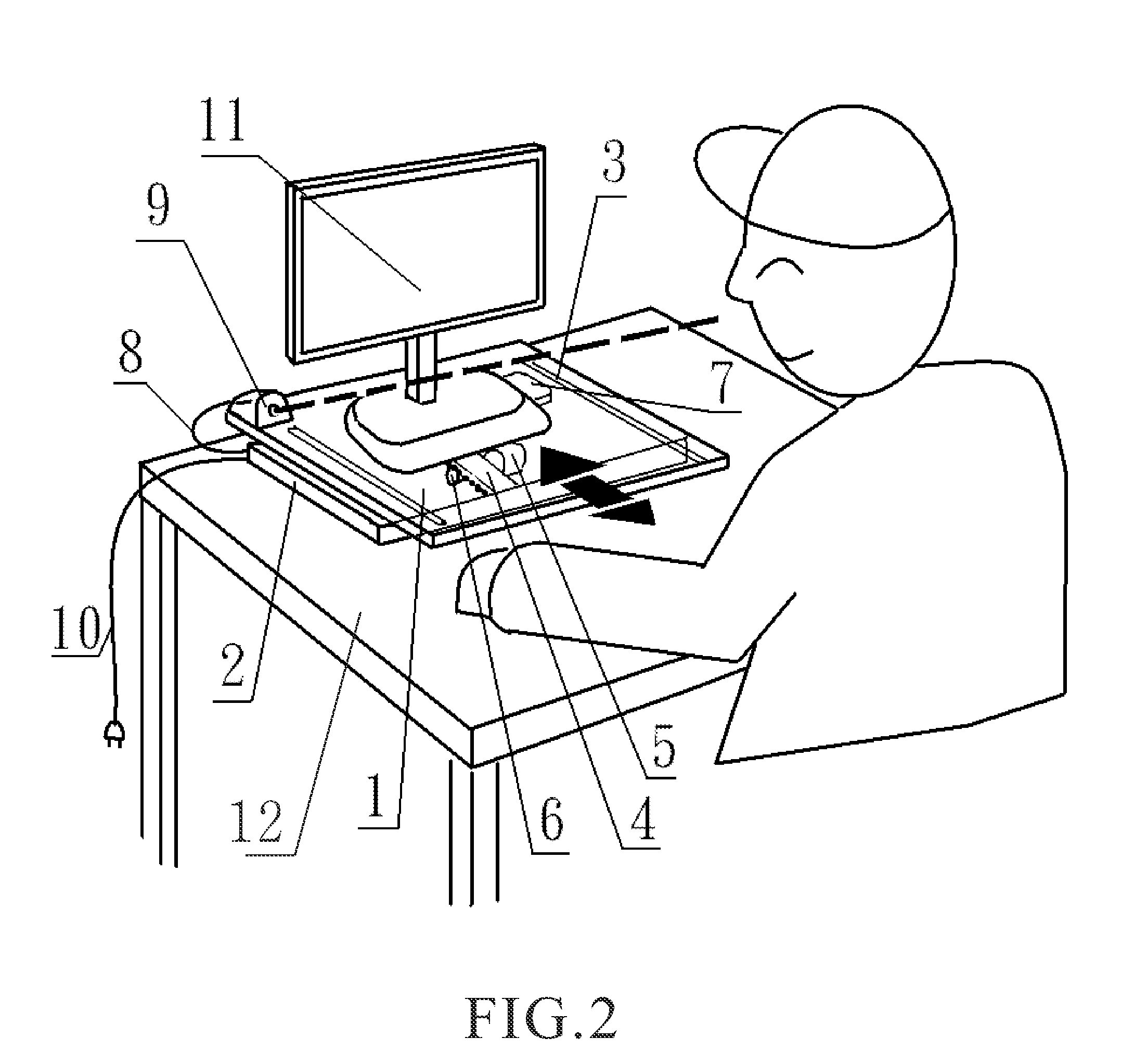
[0008]Refer to FIG. 1 and FIG. 2. The present invention proposes a mobile platform structure able to vary a viewing focal length, which comprises a mobile platform 1, a base 2, a slide rail 3, a tooth bar 4, a motor 5, a transmission gear 6, a control module 7, a signal cable 8, a telemeter 9, and a power cord 10.

[0009]The mobile platform 1 is coupled to the base 2 via the slide rail 3. The mobile platform 1 is equipped with the tooth bar 4; the motor 5 and the transmission gear 6 actuate the tooth bar 4 to move the mobile platform 1 back and forth. The motor 5, control module 7, and transmission gear 6 are arranged on the base 2. The slide rail 3 couples the mobile platform 1 and the base 2 and guides the movement of the mobile platform 1. The tooth bar 4 is arranged on the mobile platform 1 and actuated by the transmission gear 6. The motor 5 has the transmission gear 6 on the axle thereof and drives the transmission gear 6 to actuate the tooth bar 4 according to the setting store...


PUM


Abstract

A mobile platform structure able to vary a viewing focal length comprises a mobile platform, a base, a slide rail, a tooth bar, a motor, a transmission gear, a control module, a signal cable, a telemeter, and a power cord. The platform is coupled to the base via the slide rail, equipped with the tooth bar, and moved back and forth by the motor and transmission gear. The control module controls the motor to move the platform at a specified timing by a specified distance, whereby the viewing focal length of the user, who watches the display on the platform, can vary frequently lest the eyes fatigue. The telemeter is installed on the platform and detects the distance to the user's face. If the user's face approaches the platform too much, the control module controls the motor to move the platform to have an appropriate distance to the user's face.

Description

BACKGROUND OF THE INVENTION[0001]1. Field of the Invention[0002]The present invention relates to a mobile platform structure able to vary viewing focal length, carrying a display or a notebook computer, measuring the distance between the user's face and the platform when the user is watching the display on the platform, and moving the platform to an appropriate position according to the setting stored in the control module when the user's face approaches the display too much, whereby to prevent from ocular fatigue caused by overusing the eyes.[0003]2. Description of the Related Art[0004]When the user has watched a display or a notebook computer for a long time, or when the user watches the display at a distance too long or too short, the user's eyes are likely to fatigue. However, there is none effective measure to solve the abovementioned problem.SUMMARY OF THE INVENTION[0005]Accordingly, the present invention proposes a mobile platform structure able to vary a viewing focal length...

Claims


Application Information

Patent Timeline
Patent Type & Authority Applications(United States)
IPC IPC(8): H05K7/00
CPCF16M11/18F16M11/048
Inventor PAN, TU-CHENG
Owner PAN TU CHENG
Why Eureka
Try Eureka