Lever-fitting type connector

a connector type and connector technology, applied in the direction of electrical equipment, incorrect coupling prevention, coupling device connection, etc., can solve the disadvantageous damage of male and female terminals

Inactive Publication Date: 2006-12-12
YAZAKI CORP
View PDF13 Cites 8 Cited by
  • Summary
  • Abstract
  • Description
  • Claims
  • Application Information

AI Technical Summary

Benefits of technology

[0005]Under the circumstances, it is therefore an object of the present invention to provide a lever-fitting type connector capable of effecting such smooth engagement between a female connector housing and a male connector housing while maintaining respective distances among terminals in the connector housings appropriately.
[0007]According to the first aspect of the invention, with the above arrangement of the temporary engagement parts, when a pressure on the side of the first connector housing is applied on the plate body of the moving plate, the temporary engagement parts are each subjected to substantially uniform pressures, allowing the plate body to be prevented from being inclined to the second connector housing. As a result, it becomes possible to move the moving plate smoothly in engaging the first connector housing with the second connector housing and also possible to ensure appropriate distances among the terminals in the second connector housing, accomplishing certain engagement between the first connector housing and the second connector housing.
[0011]According to the third aspect of the invention, since the temporary engagement pieces in the form of repulsive arms are engaged with the engaging parts of the second connector housing, it becomes possible for the moving plate urged by the first connector housing to slide toward the second connector housing smoothly.
[0013]According to the fourth aspect of the invention, owing to the provision of the first connector housing with the holding parts, it is possible to prevent the moving plate from rattling under condition that the first and second connector housings are engaged with each other, also preventing an occurrence of abnormal noise with the enhanced reliability in engaging the first connector housing with the second connector housing.
[0017]According to the sixth aspect of the invention, owing to the engagement of the engagement projections of the second connector housing in the screw grooves formed on the lever, it is possible for an operator to manipulate the lever in its stable movement, improving the workability in engaging the first connector housing with the second connector housing.

Problems solved by technology

In some cases, there is a possibility that the male and female terminals are damaged disadvantageously.

Method used


Image

  • Lever-fitting type connector
  • Lever-fitting type connector
  • Lever-fitting type connector

Examples


Embodiment Construction

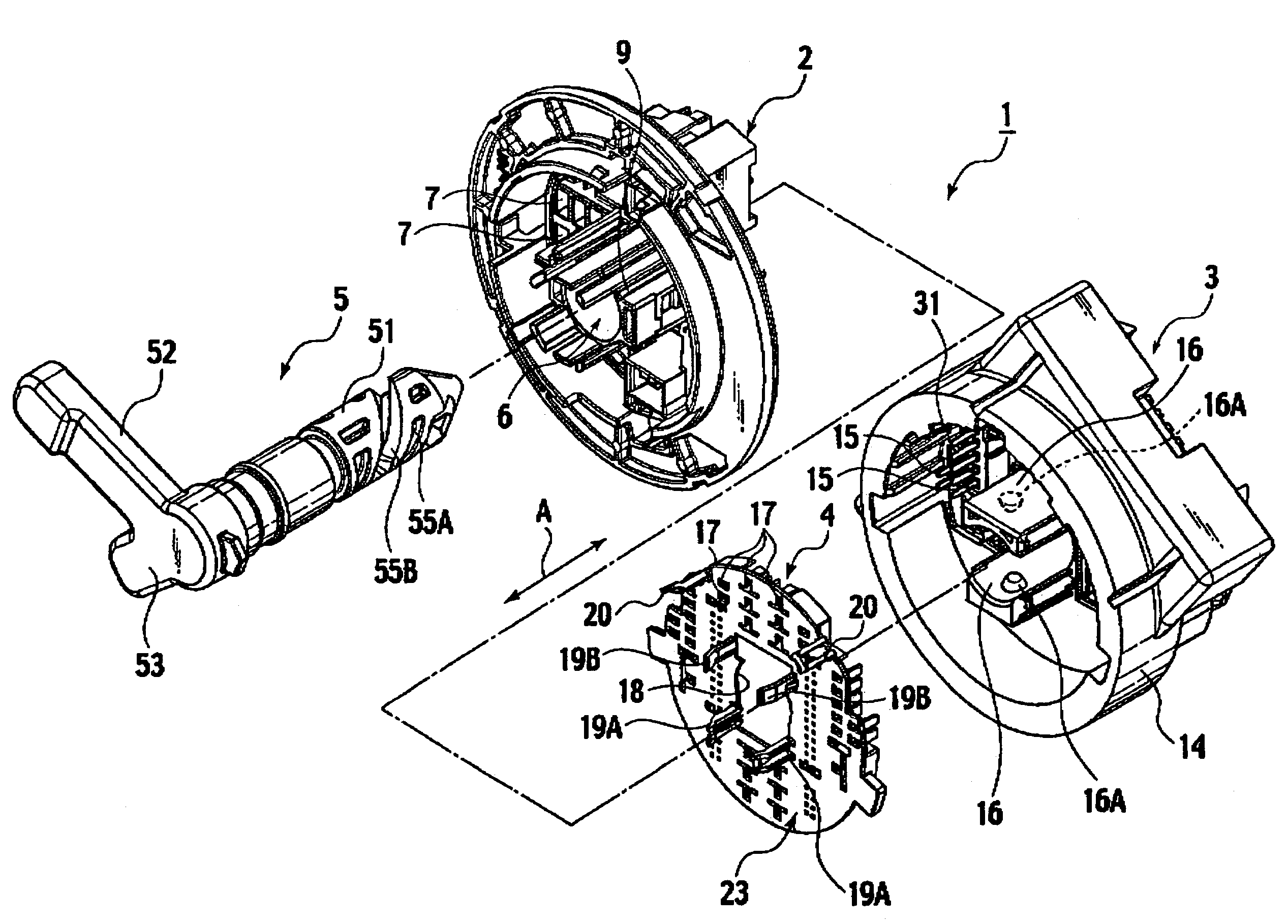
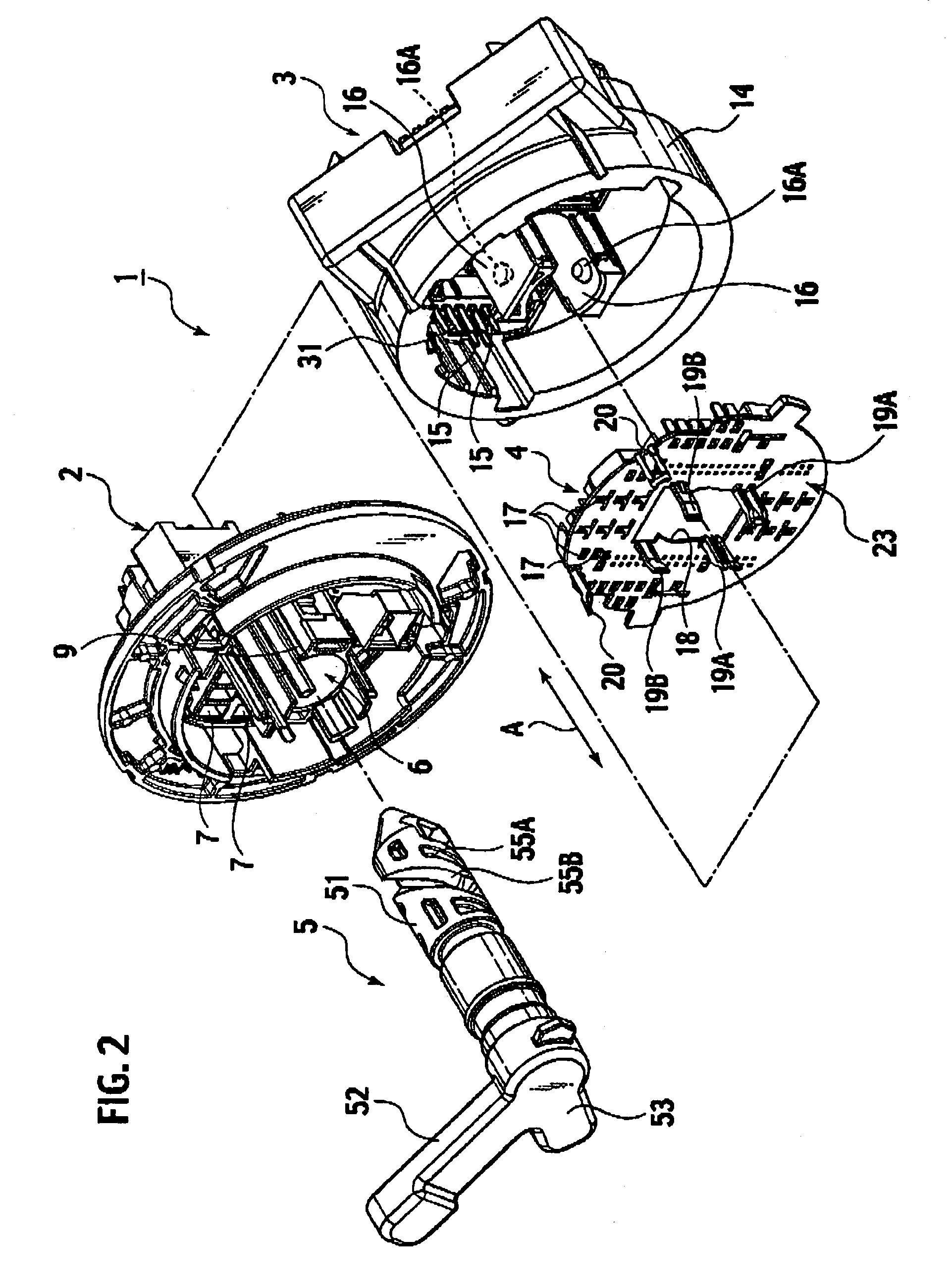
[0031]An embodiment of the present invention will be described with reference to the drawings. As shown in FIG. 2, a lever fitting type connector 1 of this embodiment is mainly formed by a female connector housing 2, a male connector housing 3, a moving plate 4 and a lever 5.

[0032][Structure of Female Connector Housing]

[0033]As shown in FIG. 2, the female connector housing 2 has a lever insertion hole 6 formed as an insertion hole that penetrates the housing 2 in a fitting direction A (shown with an arrow in the figure). Around the lever insertion hole 6, a plurality of cavities 7 are formed to penetrate the housing 2 along the fitting direction A. In the cavities 7, there are accommodated and retained not-shown female terminals respectively.

[0034]The lever insertion hole 6 is formed in a shape of bore of a cylindrical body 9 projecting from the substantial center of the female connector housing 2 (non-fitting side) in the opposite direction to the fitting direction.

[0035]On an inne...


PUM


Abstract

In a lever-fitting type connector, a moving plate is accommodated in a hood part of the male connector housing. The moving plate includes a plurality of temporary engagement parts that can be slidably and temporarily engaged with the male connector housing. These temporary engagement parts are arranged on lines perpendicular to a center axis of a lever in engagement with the male connector housing. The temporary engagement part is positioned on one side of the center axis, while the other temporary engagement parts are positioned on the other side of the center axis.

Description

BACKGROUND OF THE INVENTION[0001]The present invention relates to a lever-fitting type connector that allows female and male connector housings to be engaged to and disengaged from each other by an operator's rotational manipulation of a lever.[0002]FIG. 1 shows a bolt-fitting type connector where female and male connector housings are engaged with each other by rotation of a bolt (Japanese Patent Publication laid-open No. 11-54203). In this bolt-fitting type connector in the figure, a female connector housing 100 is provided with a bolt 102. The bolt 102 is rotatably inserted into a bolt hole 101 formed in the female connector housing 100. In engaging the female connector housing 100 with a not-shown male connector housing, the leading end of the bolt 102 is screwed into a nut fixed on the male connector housing and successively rotated with respect to the nut, so that the female and male connector housings get close to each other for integration.[0003]Note, the above-mentioned con...

Claims


Application Information

Patent Timeline
Patent Type & Authority Patents(United States)
IPC IPC(8): H01R13/627
CPCH01R13/6215H01R13/629H01R13/62938H01R13/631H01R13/62955
Inventor IKEYA, KENICHISASAKI, YASUHIRO
Owner YAZAKI CORP
Why Eureka
Try Eureka