Positioning device

a positioning device and positioning technology, applied in the direction of metal working apparatus, metal-working machine components, manufacturing tools, etc., can solve the problem of reducing positioning accuracy and gap, and achieve the effect of reliable and highly accurate positioning

Inactive Publication Date: 2007-01-30
KOSMEK LTD (JP)
View PDF17 Cites 14 Cited by
  • Summary
  • Abstract
  • Description
  • Claims
  • Application Information

AI Technical Summary

Benefits of technology

[0015]In a locking operation, after engaging the engaging hole and the engaging member with each other, the engaging member can be brought into close contact with the engaging hole. This allows the engaging hole and the engaging member to be engaged smoothly with each other as well as to be positioned with a high degree of accuracy against each other.
[0064]This invention allows foreign matter attached to contact portions and / or fitting portions of the positioning apparatus to be blown off by the above-described pressure fluid, allowing for a reliable and highly accurate positioning.

Problems solved by technology

Consequently, the fitting gap reduces the positioning accuracy.

Method used


Image

  • Positioning device
  • Positioning device
  • Positioning device

Examples


first embodiment

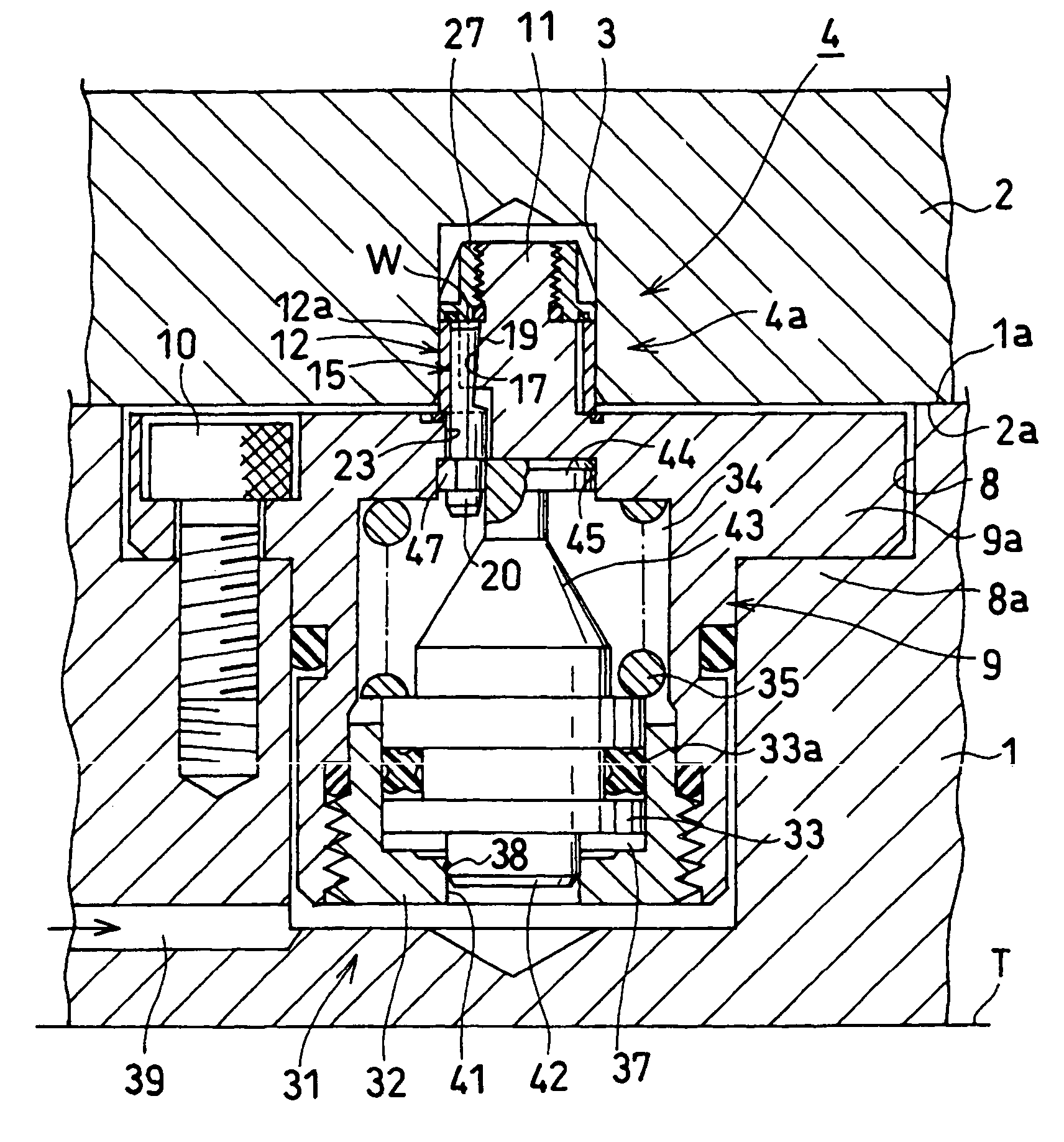
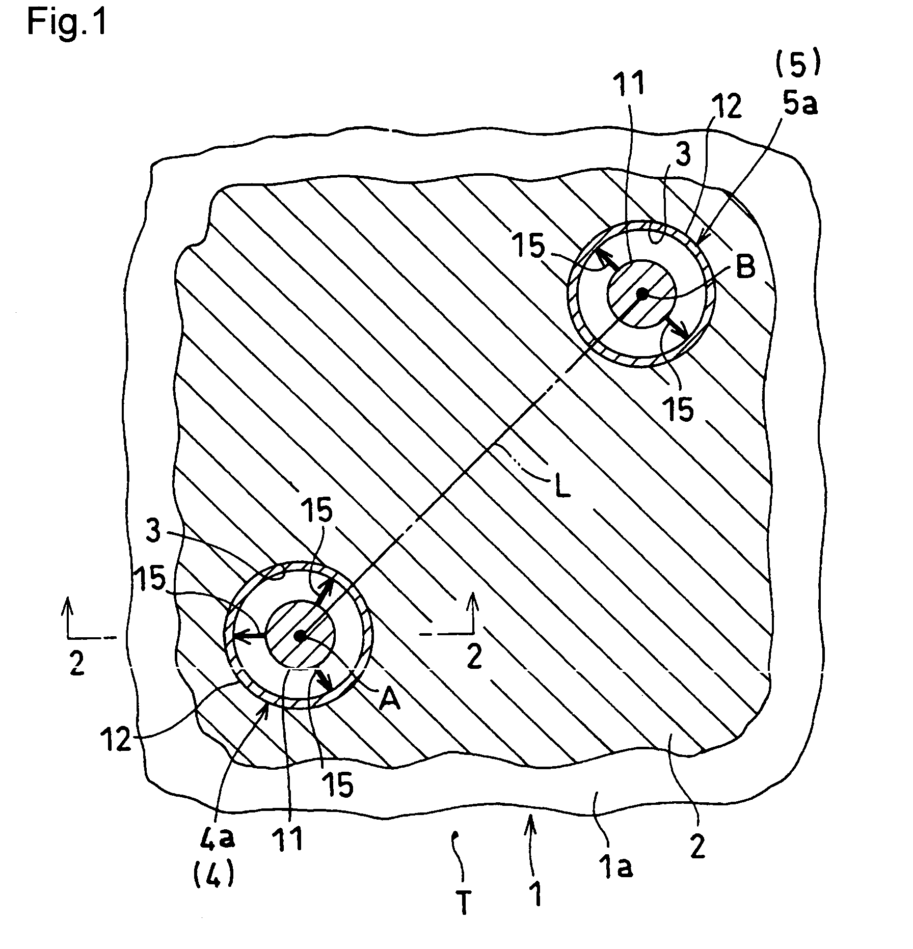
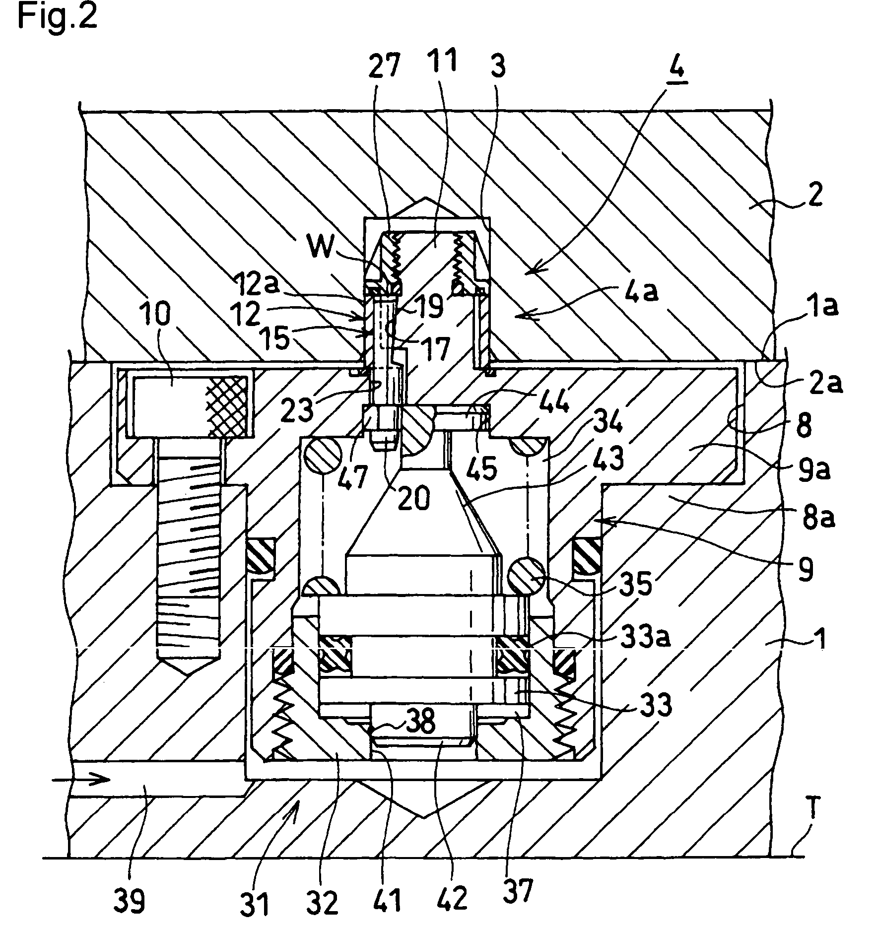
[0098]FIG. 1 through 5 show an example in which a positioning apparatus according to the present invention is applied to a pallet system as a The entire structure of the pallet system will first be described with reference to FIGS. 1 and 2. FIG. 1 is a view typically showing the basic principle of the pallet system, and particularly a horizontal cross-sectional view of the pallet system. Also, FIG. 2 is an elevational cross-sectional view of the positioning apparatus in a released state, corresponding to a view indicated by the arrow 2—2 in FIG. 1.

[0099]In this embodiment, a base plate 1 as a first block is placed on a table T of a machine tool, and it is arranged that a surface 2a to be supported of a work pallet 2 as a second block is supported onto a support surface 1a of the base plate 1, and that the work pallet 2 is aligned to the base plate 1.

[0100]In the surface 2a to be supported of the work pallet 2 are opened a plurality of precisely processed engaging holes 3. There are...

second embodiment

[0143]FIG. 12 is a view similar to FIG. 3A, showing the In this case, the wedge spaces W and the wedge members 15 are formed in such a manner as to narrow upward (toward the leading end). The lock chamber 34 is formed under the piston 33. The lower part of an upper rod 43 projected upward from the piston 33 is sealed by means of a packing 65, and the release chamber 37 is formed on the outer periphery of the upper rod 43. Then, in a locking operation, the piston 33 is driven upward by the lock spring 35 provided in the lock chamber 34. Then, the output portion 44 provided in the upper part of the upper rod 43 moves the plurality of wedge members 15 upward, and the wedge members 15 expand the elastic sleeve 12 radially.

[0144]It is noted that in the outer peripheral surface of the central pillar 11 may be arranged inclined grooves, which are inclined downward, circumferentially at substantially the same intervals instead of being formed a tapered surface 55 which narrow downward, as ...

third embodiment

[0145]FIG. 13 is a view similar to FIG. 3A, showing the In this case, the driving means 31 comprises a spring support 67 inserted in the housing 9 of the base plate 1, an operation bolt 68 supported in the central pillar 11 rotatably and screwed into the spring support 67, and the lock spring 35 for urging the spring support 67 downward. The spring support 67 is prevented from rotating centering on the axial center thereof by means of a pin 69.

[0146]In the released state shown in the figure, the operation bolt 68 is rotated and tightened using a hexagonal wrench (not shown in the figure) inserted in an operation hole 70 of the work pallet 2. Thus, the spring support 67 is moved up against the lock spring 35, and the wedge members 15 are moved upward to be released by the output portion 44 provided in the upper part of the spring support 67. When switching from the released state to a locked state, the operation bolt 68 is rotated and loosened. Then, the spring support 67 is moved d...


PUM


Abstract

A supporting face (1a) is provided on a base plate (1), a face (2a) to be supported is provided on a work pallet (2), and an engagement hole (3) is opened in the face (2a) to be supported. A core column (11) is projected upward from a housing (9) fixed to the base plate (1). An elastic sleeve (12) that fits in the engagement hole (3) is supported in a space at the outer periphery of the core column (11), on the upper face of the housing (9). Wedge spaces (W) narrowing downward are circumferentially arranged at an substantially equal intervals between the core column (11) and the elastic sleeve (12). Wedge members (15) are vertically movably inserted in each of the wedge spaces (W). Input portions (20) of the wedge members (15) are connected to an output portion (44) of an upper rod (43) of a piston (33).

Description

[0001]This application is a National Stage application of PCT / JP03 / 15139, filed Nov. 27 2003.TECHNICAL FIELD[0002]The present invention relates to an apparatus for positioning a second block such as a work pallet or a work piece in a first block such as a table of a machine tool.BACKGROUND ART[0003]This kind of positioning apparatus is generally arranged in such a manner that a circular engaging hole opened in a surface to be supported of the second block is fitted to a plug projected from a support surface of the first block (refer to Japanese Patent Public Disclosure No. 57-27640, for example).[0004]In the case of the prior art, it is necessary to provide a predetermined fitting gap between the engaging hole and the plug to fit them smoothly to each other. Consequently, the fitting gap reduces the positioning accuracy.[0005]The present invention aims at providing an apparatus capable of positioning easily with a high degree of accuracy.SUMMARY OF THE INVENTION[0006]In order to acc...

Claims


Application Information

Patent Timeline
Patent Type & Authority Patents(United States)
IPC IPC(8): B23Q3/02B23Q3/00B23Q1/00B23Q3/06B23Q3/18B23Q7/14
CPCB23Q1/009
Inventor YONEZAWA, KEITAROHARUNA, YOSUKE
Owner KOSMEK LTD (JP)
Why Eureka
Try Eureka