Power take-off control system

a control system and power takeoff technology, applied in the direction of clutches, instruments, gearing, etc., can solve the problem of gaining valuable time for modulating shaft acceleration

Active Publication Date: 2007-06-26
BLUE LEAF I P INC
View PDF20 Cites 15 Cited by
  • Summary
  • Abstract
  • Description
  • Claims
  • Application Information

AI Technical Summary

Benefits of technology

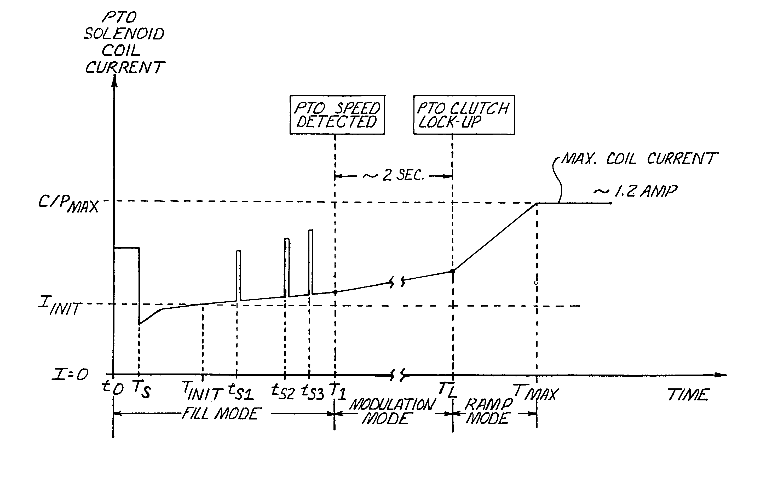
[0009]The present invention is intended to address such difficulties as might arise when the PTO shaft can be loaded with variable loads. The invention is thus directed to a control system and method for more optimally effecting engagement and operation of variable implement loads that may be applied to a PTO shaft.
[0010]By applying high amplitude / short duration current shocks, such as on top of the generally linear control curve, at different times, PTO shaft movement can be caused to occur at earlier times for heavier loads than has previously been the case. The high amplitude of the current, and the consequent high pressure applied through the clutch, and then the consequent shock effect, is effective in breaking loose static loads, such as frictions, drags, etc., and achieving earlier movement of the PTO shaft. For safety reasons, the PTO shaft is expected to start movement and then reach full speed within a time limit, such as 6 seconds. This earlier start of PTO shaft movement will gain valuable time for modulating shaft accelerations. Now that the shocks will greatly help break loose heavy static loads, the generally linear control curve can be made even more gentle / flat without being concerned that it takes too long to engage heavy load applications. The combination of flatter linear control and longer modulation of acceleration is beneficial in achieving smoother PTO engagement for any load conditions.
[0011]The short duration of the applied shocks ensures that the overall energy level remains low, however, which not only protects the PTO shaft but also ensures that the acceleration of the PTO shaft will be determined primarily by the generally linear control curve and not by the current shock. By employing this technique, heavier static loads can be more readily broken loose, yet smooth PTO shaft acceleration can be achieved.
[0016]Still heavier shocks can be made at still later times and additional load type designations made, as may be desired. A maximum time can also be established for detecting movement of the PTO shaft, with non-movement by such time being considered indicative of an overload condition. In such event, the control system can then effect a termination of the engagement operation so as to avoid damage to the PTO shaft or the vehicle engine.

Problems solved by technology

This earlier start of PTO shaft movement will gain valuable time for modulating shaft accelerations.

Method used


Image

  • Power take-off control system
  • Power take-off control system
  • Power take-off control system

Examples


Embodiment Construction

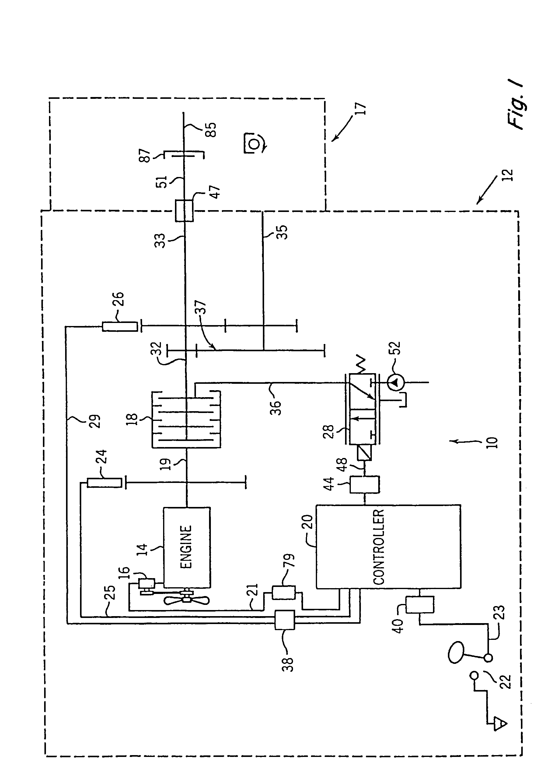
[0029]FIG. 1 depicts an embodiment of a power take-off (PTO) clutch control system 10 for an agricultural vehicle (such as a tractor schematically represented by the dashed line labeled 12) that includes the present invention. With the exception of the PTO clutch control system 10, tractor 12 may be a conventional agricultural tractor of the type including an engine 14 having conventional accessories such as an alternator 16. Engine 14 is the power source for tractor and, in addition to providing power to the drive wheels (not shown) of tractor 12, provides the power to apply rotational motion to a multi-plate hydraulically actuated PTO clutch 18. Depending upon whether PTO clutch 18 is engaged, power from engine 14 may in turn be transmitted to an output shaft 32. Output shaft 32 is shown directly coupled to a 1000 RPM PTO (high speed PTO) shaft 33 and also is shown coupled to a 540 RPM PTO (low speed PTO) shaft 35 by a reduction gear 37. In alternative embodiments, high speed PTO ...


PUM


Abstract

A control system and method for detecting variable load types and controlling the operation of a PTO clutch to effect engagement of the clutch with variable loads, and especially to more optimally effect the engagement of a clutch with a heavy load is disclosed. The control system includes a controller that receives input and output clutch shaft speed signals and generates control signals to control the pressure applied by the clutch. When heavier loads are applied to the PTO shaft, during the time when control signals are being generated before detection of initial movement of the output shaft, the controller generates one or more shock signals of short duration to cause momentary applications of significantly greater pressure to the clutch in order to break loose the applied load. Based upon the time of detection of initial movement by the output shaft, load categorization can be made, and control signals that are thereafter generated before lockup may be dependent, in part, upon the determined load categorization.

Description

TECHNICAL FIELD[0001]The present invention relates to a power take-off (PTO) control system and method for more optimally engaging and operating loads applied to the PTO shaft, especially for an agricultural vehicle such as a tractor. In particular, the present invention relates to a control system and method for detecting variable load types and controlling the operation of a PTO clutch to effect engagement of the clutch with variable loads, and especially to more optimally effect the engagement of a clutch under extreme conditions, such as a very light load, a very heavy load, and / or overrun clutches.BACKGROUND ART[0002]PTOs are used on many types of vehicles, including on agricultural vehicles such as tractors, to provide power for equipment or implements, such as, for agricultural purposes, combines, mowers, balers, forage harvesters and spreaders.[0003]Modern tractors commonly have horsepower ratings in excess of 100 horsepower. However, the shaft sizes for PTOs have not change...

Claims


Application Information

Patent Timeline
Patent Type & Authority Patents(United States)
IPC IPC(8): F16H37/00F16D48/06
CPCF16D48/066F16D2500/1026F16D2500/10437F16D2500/1045F16D2500/111F16D2500/30406F16D2500/30426F16D2500/3067F16D2500/50287F16D2500/70406F16D2500/70418
Inventor HOU, YANMINGSVENDSON, DARREL J.
Owner BLUE LEAF I P INC
Why Eureka
Try Eureka