
Self-Illuminating Fire Door

a self-illuminating, fire door technology, applied in the direction of illuminated signs, display means, instruments, etc., can solve the problems of hidden threat of fire accidents, aging electrical appliances, and putting a lot of weight on cities

Inactive Publication Date: 2013-06-13
SHENZHEN GUANGAN FIRE FIGHTING & DECORATION ENG
View PDF12 Cites 27 Cited by
  • Summary
  • Abstract
  • Description
  • Claims
  • Application Information

AI Technical Summary

Benefits of technology

The present invention relates to a self-illuminating fire door that can provide guidance to people in dark environments or during night-time when there is no visible light available. The fire door has a simple construction and is easy to install and promote. It can block the spread of fire and provides illumination to guide people to the exit route, saving valuable time during escape. The technical effects of the invention are that it provides a guiding effect in assisting escape and promoting safety during fire outbreaks.

Problems solved by technology

The large cities in the world are loaded with high rise buildings and high population density, and therefore much weight is put onto the cities.
In addition, problems of aging electrical appliances, ineffective safety and precaution measures, human damage, terror attack and etc. have posed a hidden threat to fire accidents which may be easily occurred in high rise buildings in the cities.
Fire occurred in high rise buildings will cause direct threat to residents or tenants in higher levels.
However, conventional fire door fails to provide obvious and prominent guiding mark, especially when the fire is occurred at night, and people cannot see clearly and locate the fire door, and may therefore miss the best timing for escape.

Method used


Image

  • Self-Illuminating Fire Door
  • Self-Illuminating Fire Door
  • Self-Illuminating Fire Door

Examples


exemplary embodiment 1

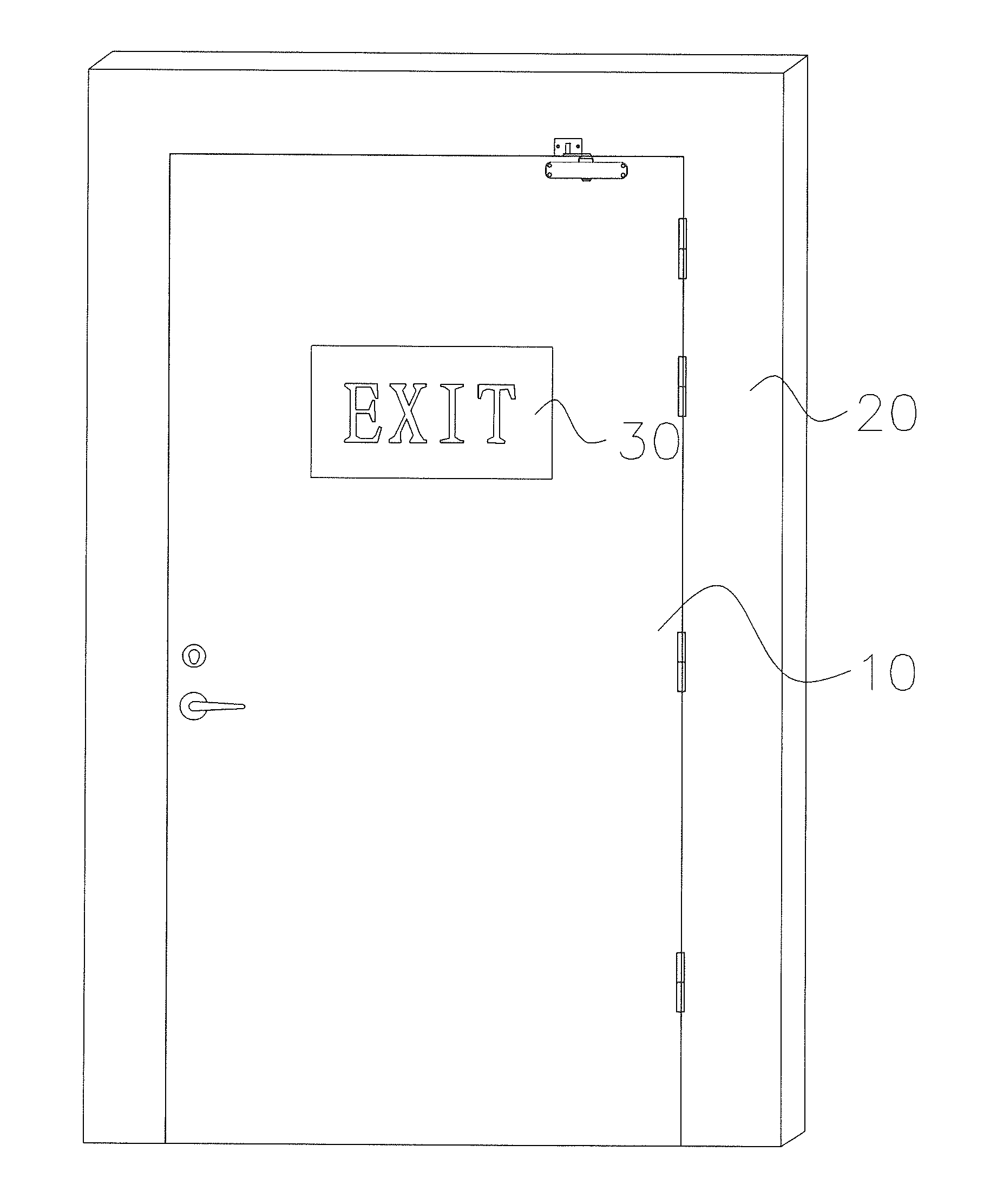
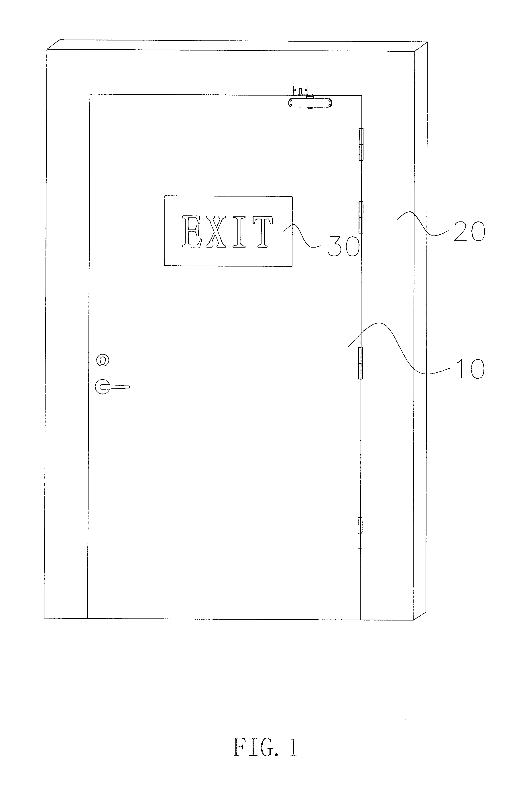
[0026]Referring to FIG. 1 of the drawings, the front surface of the front side of the door body 10 further defines a center portion at which the self-illuminating member 30 is positioned. The self-illuminating member 30 is made in self-illuminating material which is capable of providing illumination under a dark condition. The self-illuminating member 30 can be constructed into a block unit, a rod unit or a flat film body unit. In this embodiment, the self-illuminating member 30 is constructed into a block unit which can be designed to form a safety sign in a graphical form or in a text form, such as “” in Chinese, “EXIT” in English or “” in graphical form. The safety sign is a block unit and is mounted firmly onto the center portion of the front surface of the front side of the door body 10. The self-illuminating member 30 is made of alkaline earth alluminate material to form a light-storing type self-illuminating block unit which is capable of absorbing and storing light energy fr...

exemplary embodiment 2

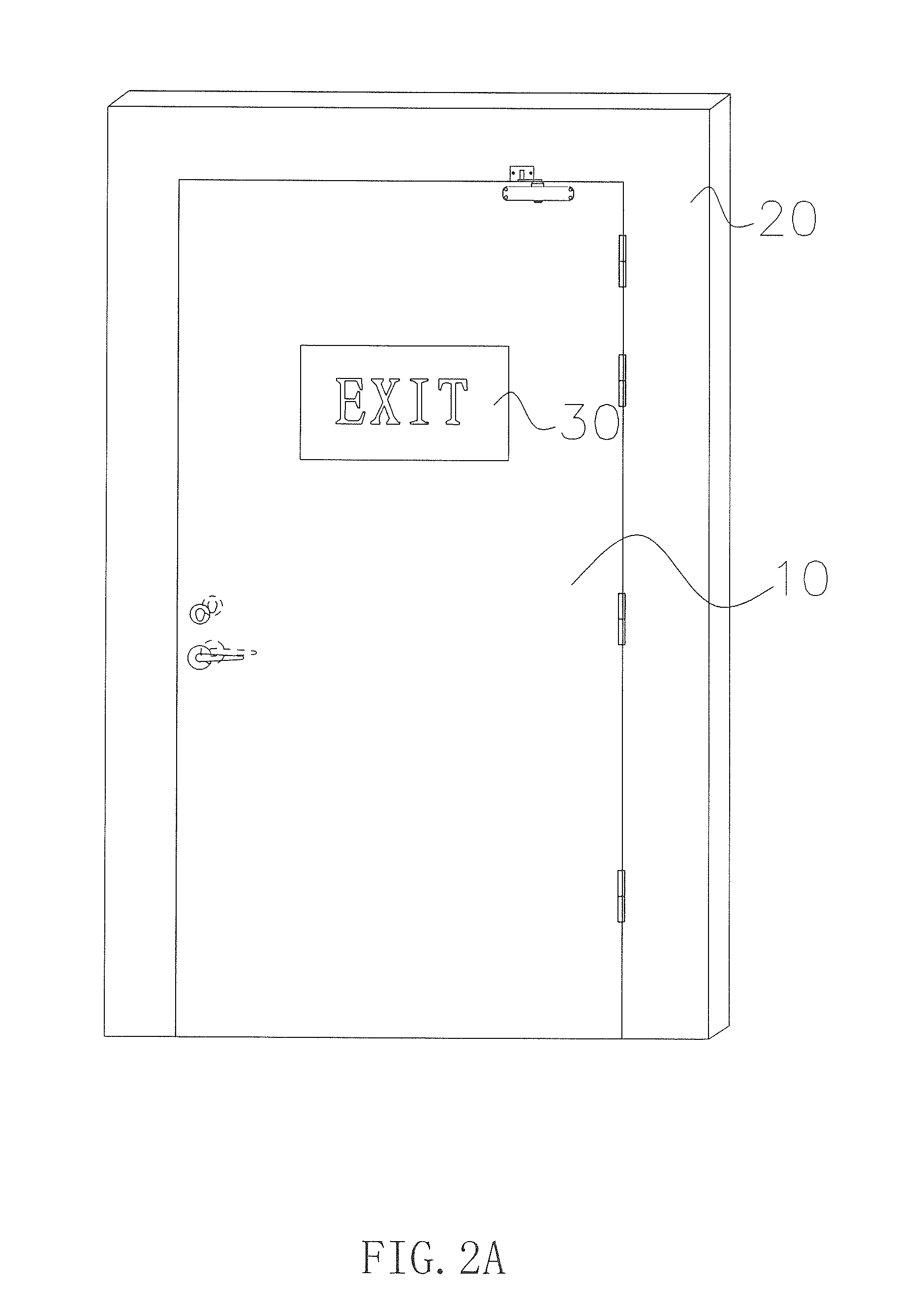
[0027]Referring to FIGS. 2A and 2B of the drawings, the self-illuminating fire door in this embodiment 2 according to the preferred embodiment of the present invention includes a structural construction identical to that of the exemplary embodiment 1 except that the front surface of the front side of the door body 10 further defines a middle portion at which the self-illuminating member 30 is positioned, as shown in FIG. 2A, and the rear surface of the rear side of the door body 10 further defines a middle portion at which the self-illuminating member 30 is positioned, as shown in FIG. 2B.

exemplary embodiment 3

[0028]Referring to FIGS. 3A and 3B of the drawings, the self-illuminating fire door in this embodiment 3 according to the preferred embodiment of the present invention includes a structural construction identical to that of the exemplary embodiment 1 except that the self-illuminating member 30 is mounted onto a center portion of a front surface of a front side of the door frame 20, as shown in FIG. 3A; and is mounted onto a center portion of a rear surface of a rear side of the door frame 20, as shown in FIG. 3B.


PUM


Abstract

A self-illuminating fire door includes a door body (10) and a door frame (20), each having a front and a rear sides respectively, includes a self-illuminating member (30) on at least one side of the door body (10) and the door frame (20). The self-illuminating member (30) is made in self-illuminating material and constructed into a block unit, a rod unit or a flat film body unit. The block unit or the rod unit is mounted onto the door body (10) or the door frame (20) at one or both sides. The flat film unit is stick or bonded onto the door body (10) or the door frame (20) at one or both sides. The self-illuminating material is alkaline earth alluminate material, a light-storing type self-illuminating material. The fire door can illuminate under a dark condition or at night, thereby guiding people to exit route to escape from the fire.

Description

BACKGROUND OF THE PRESENT INVENTION[0001]1. Field of Invention[0002]The present invention relates to fire door in fire control, and more particularly to a fire door which is capable of self-illuminating under dark environmental condition or at night.[0003]2. Description of Related Arts[0004]Nowadays, the pace of industrial development and urbanization become faster and faster. The large cities in the world are loaded with high rise buildings and high population density, and therefore much weight is put onto the cities. The dramatic increase in population and the fast-paced industrial development have led to a great increase in electric usage. In addition, problems of aging electrical appliances, ineffective safety and precaution measures, human damage, terror attack and etc. have posed a hidden threat to fire accidents which may be easily occurred in high rise buildings in the cities. Fire occurred in high rise buildings will cause direct threat to residents or tenants in higher lev...

Claims


Application Information

Patent Timeline
Patent Type & Authority Applications(United States)
IPC IPC(8): E06B5/16G09F13/20
CPCG09F13/20G09F2013/0459G09F13/04G09F2013/05
Inventor LI, SHAOBIN
Owner SHENZHEN GUANGAN FIRE FIGHTING & DECORATION ENG
Learn More