Ink tank

a technology of ink tanks and ink tanks, applied in printing and other directions, can solve the problems of increasing the number of ink tanks, increasing the frequency of user replacement of ink tanks, and failure to smooth the contact section of the information transmission system at the beginning, so as to improve the attachment property of ink tanks

Inactive Publication Date: 2011-09-06
CANON KK
View PDF29 Cites 15 Cited by
  • Summary
  • Abstract
  • Description
  • Claims
  • Application Information

AI Technical Summary

Benefits of technology

[0019]According to the present invention, an ink supply port is disposed on the opposite side to the side where a positioning section for an electric contact is disposed, having a central axis therebetween. When the ink tank is attached to a printing apparatus, the ink tank is tilted toward the side of the positioning section for the electric contact due to a reactive force applied to an ink receiving section provided on the printing apparatus, the reactive force oriented to the opposite direction of the attachment direction and generated at the time of connecting the ink tank. As a result, the positioning section for the electric contact is smoothly engaged with a positioning section of an attachment section corresponding thereto. In this way, it is possible to improve the attachment property of the ink tank and to establish secure connection of the contact section for an ink supply system and the electric contact section.

Problems solved by technology

Such a configuration causes an increase in the number of ink tanks, whereby the frequency of tank replacing operations by a user is increased.
Occurrence of such a tilt of the ink tank may lead to a failure in smooth engagement of the contact section for the information transmission system at the beginning.
Accordingly, there are problems that the attachment property of the ink tank may decrease, and that electric connection may be made inaccurately.
While these problems apply also to the case of an ink tank configured to contain a single-color ink, the problems are even more critical in the case of an ink tank configured to contain inks of multiple colors.
In addition, without careful arrangement of the positions of the multiple ink supply ports, the ink tank may be attached while tilting or rolling from side to side.

Method used


Image

  • Ink tank
  • Ink tank
  • Ink tank

Examples


second embodiment

[0113]It is to be noted that the present invention is not limited only to the above-described embodiment, and the invention may apply various modifications.

[0114]FIG. 12A shows an ink tank according to a second embodiment of the present invention.

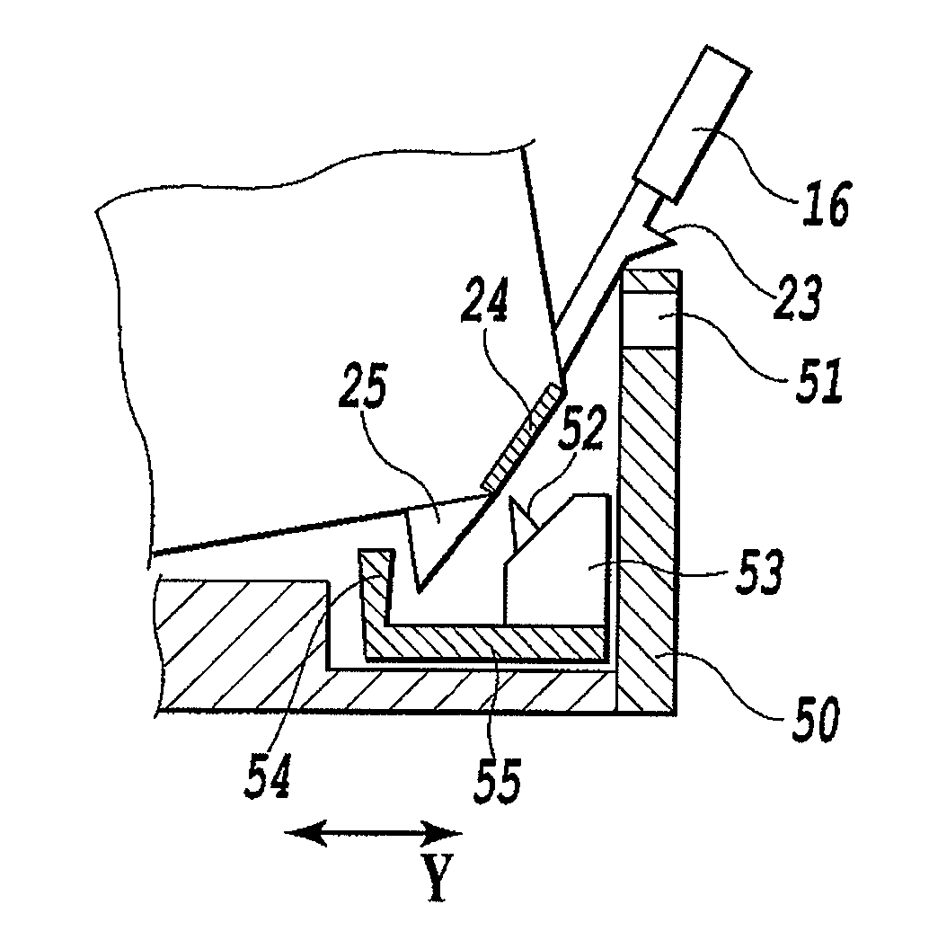
[0115]In a case where an ink tank is attached to the holder unit 50, the ink tank of the first embodiment is configured to insert the first engagement sections 22 provided on the back side of the tank into the first fitting sections 35 of the holder and then to perform a rotating operation around the first engagement sections 22. The holder unit 50 is provided with a guide plate 111 for regulating the direction of insertion so that the back side provided with the first engagement sections is inserted in the first place when attaching the ink tank. The reason for providing the plate is to lead the user to put the first engagement sections provided on the back side of the ink tank below the plate and then to push the latch lever after inserti...


PUM


Abstract

An ink tank provided with a supply port for supplying the ink contained therein and an electric contact for information transmission is smoothly and securely attached to an attachment section of a printing apparatus while achieving secure connection of an electric contact section at the same time. The ink tank is configured to be attachable to the attachment section by positioning a first engagement section at a first fitting section on the attachment section, and then by rotating the ink tank around the positioned first engagement section to lock a second engagement section to a second fitting section on the attachment section. The supply port and a positioning section for the contact are disposed on the bottom face of the ink tank so as to be on the respective two sides of the center line in the width direction of the ink tank therebetween.

Description

BACKGROUND OF THE INVENTION[0001]1. Field of the Invention[0002]The present invention relates to an ink tank, and, more specifically, to an ink tank to be employed to an inkjet printing apparatus.[0003]2. Description of the Related Art[0004]Along the advance of image quality of printing in recent years, commonly employed in inkjet printing apparatuses is a method of increasing the number of ink colors used for printing in order to improve the image quality targeting for photographic image quality. A method of providing multiple tanks is widely used in a desktop printing apparatus, the tanks prepared for different colors and being independently detachable. Such a configuration causes an increase in the number of ink tanks, whereby the frequency of tank replacing operations by a user is increased. Moreover, as the ink tanks are provided independently, the wall thickness of each of the ink tanks has a great influence on the size of the printing apparatus.[0005]Accordingly, from the vie...

Claims


Application Information

Patent Timeline
Patent Type & Authority Patents(United States)
IPC IPC(8): B41J2/175B41J2/14
CPCB41J2/17513B41J2/1752B41J2/17523B41J2/17553
Inventor HAYASHI, HIROKIKITABATAKE, KENJI
Owner CANON KK
Why Eureka
Try Eureka