Heat sink equipped with a vapor chamber

a heat sink and vapor chamber technology, applied in the field of heat sinks, can solve the problems of hampering the heat dissipation effect of the heat sink and the heat transfer effect suffers, and achieve the effect of quick and effective heat transfer

Inactive Publication Date: 2012-08-23
CHIA CHERNE IND CO LTD
View PDF6 Cites 38 Cited by
  • Summary
  • Abstract
  • Description
  • Claims
  • Application Information

AI Technical Summary

Benefits of technology

[0005]Therefore, the primary object of the present invention is to provide a heat sink that can quickly and effectively transfer heat outside to achieve desired cooling effect.

Problems solved by technology

As a result, heat transfer effect suffers.
All these hamper heat dissipation effect of the heat sink.

Method used


Image

  • Heat sink equipped with a vapor chamber
  • Heat sink equipped with a vapor chamber
  • Heat sink equipped with a vapor chamber

Examples


Embodiment Construction

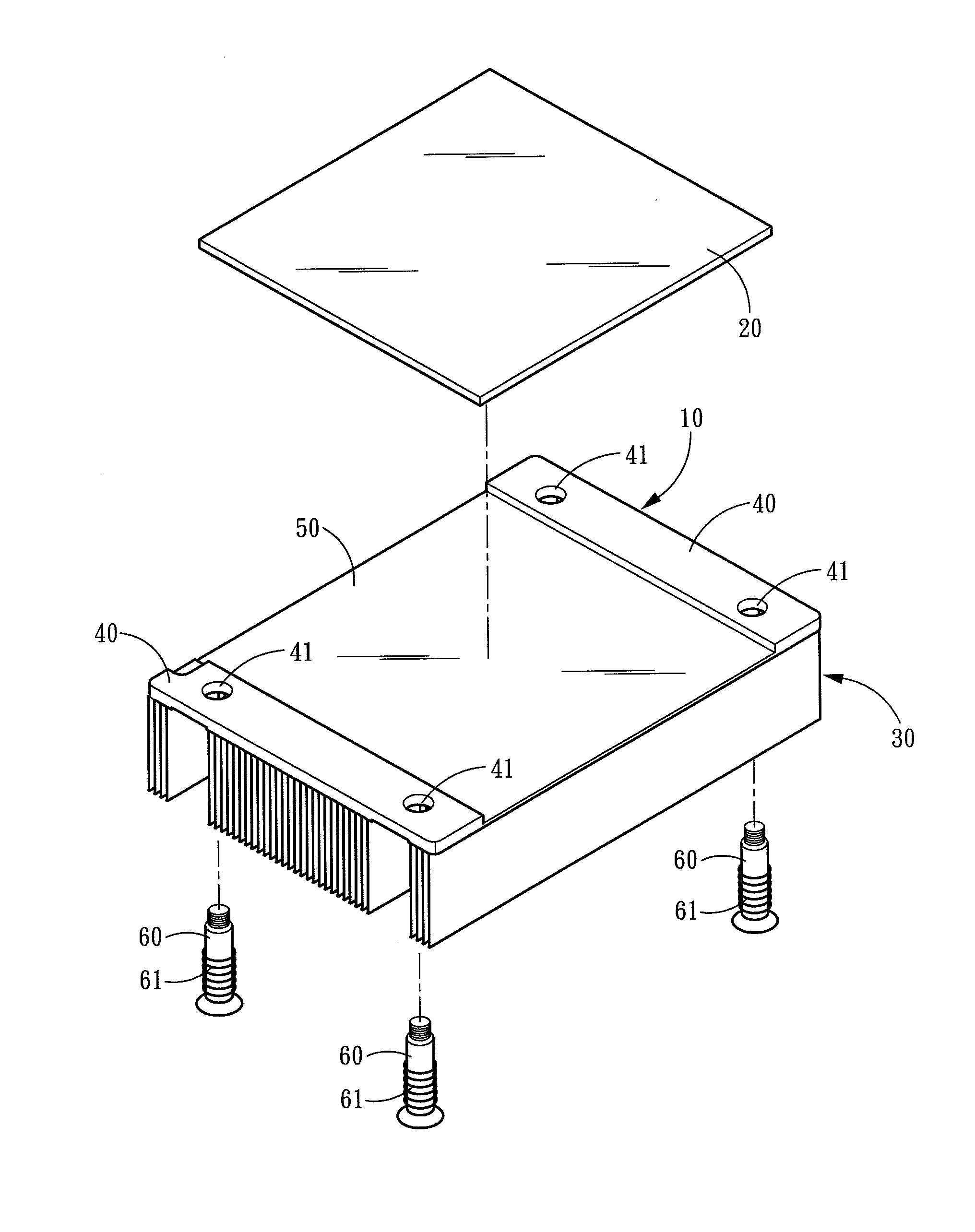
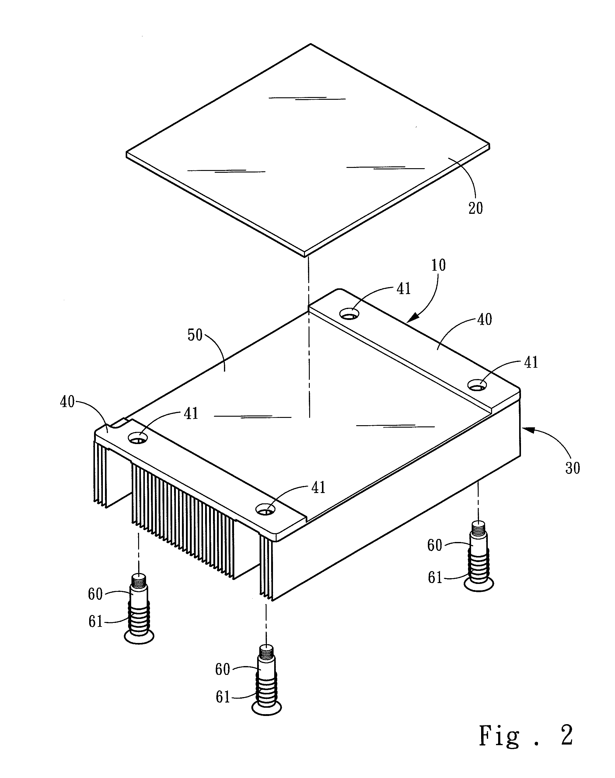
[0015]Please refer to FIGS. 2 and 3, the present invention aims to provide a heat sink equipped with a vapor chamber. The heat sink includes a heat conduction plate 10 and a vapor chamber 20. The heat conduction plate 10 has one side formed integrally a plurality of radiation fins 30 and another side with two lateral edges formed respectively and integrally a fastening portion 40. The two fastening portions 40 are interposed by a recess 50 to bond the vapor chamber 20. Each fastening portion 40 has at least one aperture 41 run through by at least one screw 60 coupled with a spring 61 to fasten to a printed circuit board (PCB in short, not shown in the drawings) to allow the vapor chamber 20 in contact with a heat generation element (not shown in the drawings).

[0016]Refer to FIGS. 4 and 5 for another embodiment of the invention. The heat conduction plate 10 has a latch flange 52 respectively on a front side and a rear side of the recess 50, and an airtight compartment 51 dug downward...


PUM


Abstract

A heat sink equipped with a vapor chamber includes a heat conduction plate and a vapor chamber. The heat conduction plate has one side formed integrally a plurality of radiation fins and another side with two lateral edges formed respectively and integrally a fastening portion. The two fastening portions are interposed by a recess to bond the vapor chamber. Each fastening portion is fastened to a printed circuit board through at least one screw to allow the vapor chamber to contact a heat generation element. The fastening portion is integrally formed at a desired thickness, thus has sufficient strength to withstand the fastening force of the screw to prevent tight sealing between the vapor chamber and heat generation element affected by deformation of the heat conduction plate. Thereby the vapor chamber can smoothly contact the heat generation element to rapidly transfer heat outside.

Description

FIELD OF THE INVENTION[0001]The present invention relates to a heat sink and particularly to a heat sink equipped with a vapor chamber.BACKGROUND OF THE INVENTION[0002]Please refer to FIG. 1, a conventional heat sink includes a heat conduction plate 1 and a vapor chamber 2. The heat conduction plate 1 has one side formed a plurality of radiation fins 3 and another side bonded to the vapor chamber 2, and two lateral sides fastened to a printed circuit board (PCB in short, not shown in the drawing) through at least one screw 4. The vapor chamber 2 is in contact with a heat generation element (not shown in the drawing) of the PCB, and is hollow and vacuumed to seal heat transfer fluid 5 (pure water) inside which can rapidly transfer heat through phase transition between liquid and gas states. Hence the heat generated by the heat generation element can be quickly spread by the vapor chamber 2 to the radiation fins 3 to dissipate the heat to lower the temperature.[0003]To save material, ...

Claims


Application Information

Patent Timeline
Patent Type & Authority Applications(United States)
IPC IPC(8): F28F7/00
CPCF28D15/0233F28D15/0275F28D2021/0029H01L23/427H01L2924/0002H01L2924/00
Inventor SHIH, DAVID
Owner CHIA CHERNE IND CO LTD
Why Eureka
Try Eureka