
Computer system performance analysis

a computer system and performance analysis technology, applied in the field of computer system performance analysis, can solve the problem that existing performance analysis tools only can provid

Inactive Publication Date: 2012-08-23
IBM CORP
View PDF21 Cites 5 Cited by
  • Summary
  • Abstract
  • Description
  • Claims
  • Application Information

AI Technical Summary

Benefits of technology

The invention provides a new method and device for analyzing computer system performance. It can identify hotspots more accurately and improve recognition rate and accuracy. The method and device can also provide portable comments for system performance analysis results. Overall, the invention can help improve computer system performance analysis and make it more efficient.

Problems solved by technology

As mentioned above, however, those existing performance analysis tools only can provide sorted lists of instruction, function or module based performance statistics, rather than instruction block (instruction cluster) based statistics.

Method used


Image

  • Computer system performance analysis
  • Computer system performance analysis
  • Computer system performance analysis

Examples


example 1

[0087]One application of the embodiment of this invention is to recognize hotspots to optimize system performance. FIGS. 9 and 10 are schematic views of the examples, in which hotspots are identified from performance analysis result according to the embodiments of this invention.

[0088]FIG. 9 shows a portion of the list of the example performance analysis result. As shown in FIG. 9, the tick density (tDensity) of the cluster with clusterNo=13 significantly higher than other clusters. Therefore, the cluster with clusterNo=13 is recognized as a hotspot. In the visual list shown in FIG. 10, the hotspot is highlighted by a ring.

example 2

[0089]FIG. 11 is a schematic view of the example of identifying large warm areas from performance analysis result according to the embodiments of this invention. Large warm areas are code areas having large instruction blocks that are intensively executed even though each instruction may only consume a few of cycles. Large warm areas have performance improvement potential as well.

[0090]As shown in FIG. 11, the clusters with clusterNo 0 and 1 are recognized as large warm areas and are highlighted with rings.

example 3

[0091]An embodiment of this invention can also recognize code reordering potential areas. For example, two or more clusters can be found within the system performance analysis result as code reordering potential areas, which pertain to one symbol and have smaller address spans and larger instruction cache miss density. Instruction cache miss density can be calculated as the rate of the count of instruction cache miss to the address span of a corresponding cluster.

[0092]In one example implementation, through reordering process, two code reordering potential areas are rearranged into adjacent areas, as a result, hotspots can be reduced, and 5% gain is achieved.

[0093]This invention can be implemented as a computer program product comprising all or part of codes for implementing the method and device for computer system performance analysis according to an embodiment. Those codes can be stored within the memories of other computer systems before use, for example, within hard disks or re...


PUM


Abstract

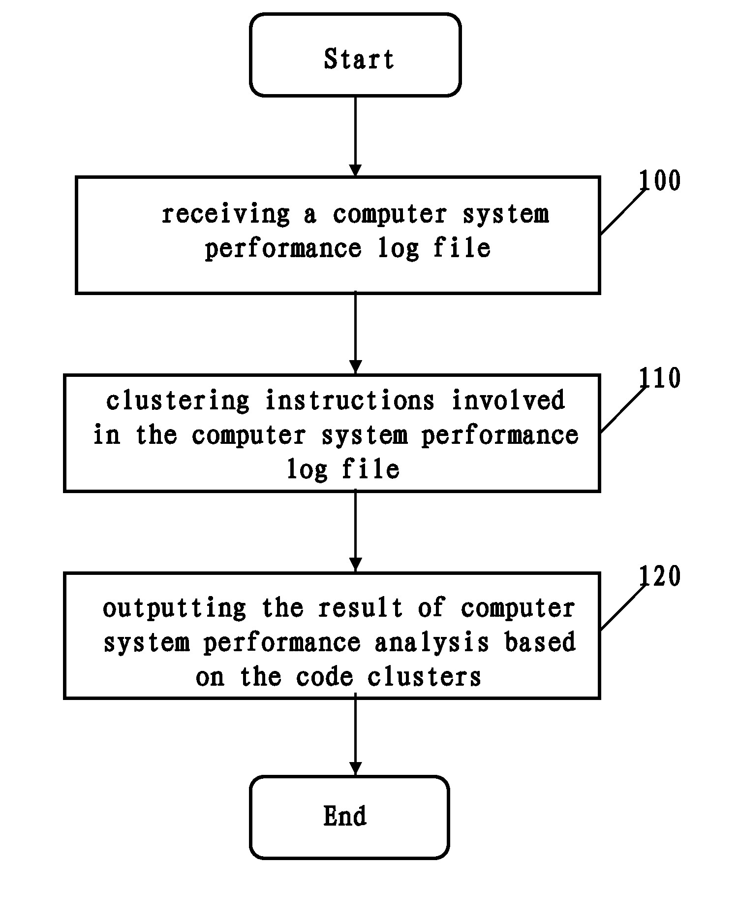
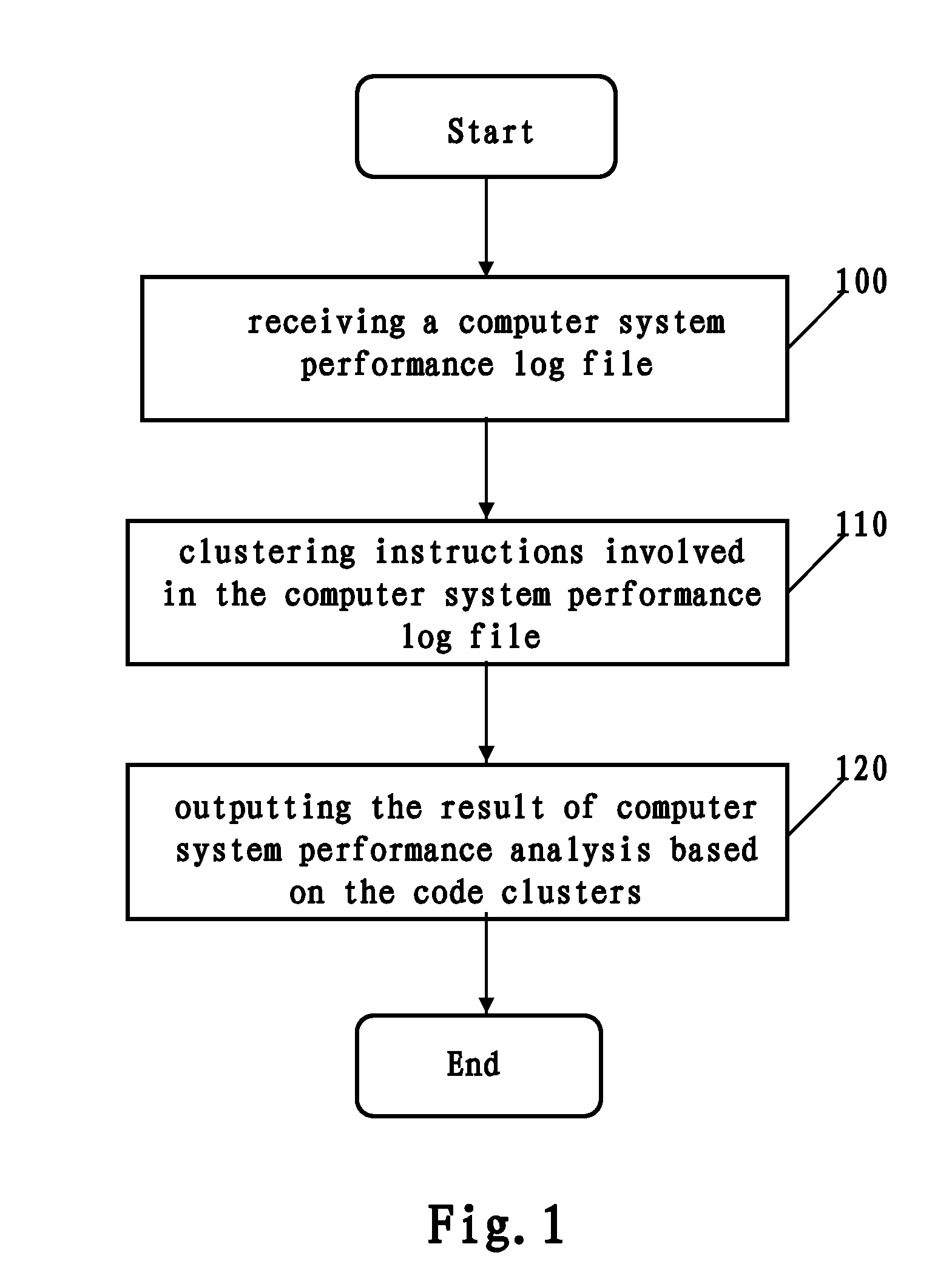
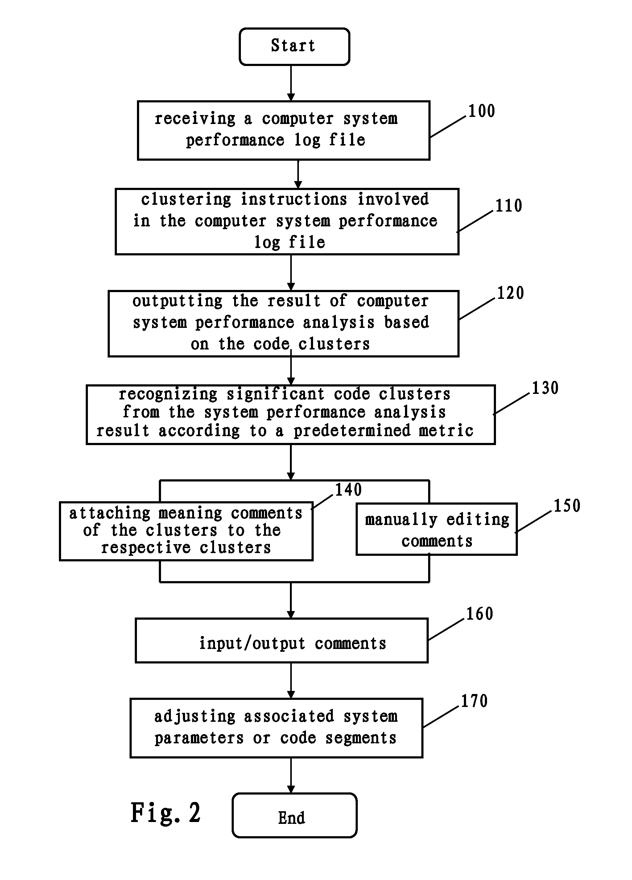
This invention relates to a method and device for computer system performance analysis. All instructions are split into clusters based on significant offset gaps in top-down processing steps. Comments on instruction clusters can be generated automatically or can be edited manually. The comments can be shared among users for the achievement of portability. Significant clusters can be recognized as hotspots based on predetermined metrics.

Description

[0001]The present application is a continuation of patent application Ser. No. 12 / 964,869, which is co-pending with the present application.TECHNICAL FIELD[0002]The present invention relates to computer system performance analysis, and more specifically, to a method, program product, and device for performing computer system performance analysis.DESCRIPTION OF THE RELATED ART[0003]It is valuable for system designers, software developers, users or data center operators to analyze and then improve performance deficiencies of their systems (e.g., hardware, software and services) from sampled data of hardware with low cost.[0004]There are many system performance analysis tools, such as Oprofile, Intel Vtune, IBM VPA, and the like. (Intel and Vtune are trademarks of Intel Corporation in the United States, other countries, or both. IBM is a registered trademark of international Business Machines Corporation in the United States and other countries). Such tools may provide visual system pe...

Claims


Application Information

Patent Timeline
Patent Type & Authority Applications(United States)
IPC IPC(8): G06F17/30
CPCG06F11/3409G06F2201/88G06F2201/865G06F11/3452
Inventor HEISIG, STEPHEN JOHNWANG, YAN QIXIAO, JINGYUAN, YUZOU, JIA
Owner IBM CORP
Learn More