Cleaner head for a surface treating appliance

a cleaning head and surface treatment technology, applied in the direction of suction cleaners, cleaning equipment, suction nozzles, etc., can solve the problems of air leaking around the connection, reducing the pick-up performance of the cleaner head, turbulence and noise, etc., and achieve the effect of reducing the length of the cleaner head

Active Publication Date: 2012-08-30
DYSON TECH LTD
View PDF0 Cites 66 Cited by
  • Summary
  • Abstract
  • Description
  • Claims
  • Application Information

AI Technical Summary

Benefits of technology

[0008]As the connectors for connecting together the front conduit and the rear conduit lie outside a fluid flow path passing through the conduits, the connectors may have any desired configuration without requiring any seals for preventing fluid from leaking between the connectors. In a preferred embodiment, the front conduit comprises a pair of arms which extend towards the rear conduit, and the rear conduit comprises a shaft which is received between the arms. A bolt, pin or other connecting member may be provided for connecting the shaft to the arms so that the shaft can rotate relative to the arms. Alternative, the connectors may be connected together by means of a snap-fit connection. A relatively simple seal may then be provided between the elbow sections to prevent fluid from leaking between the elbow sections.
[0019]In a second aspect, the present invention provides a conduit assembly for a cleaner head of a surface treating appliance, the conduit assembly comprises a front conduit, a rear conduit pivotably connected to the front conduit for movement between a raised position and a lowered position, and a chassis for supporting the front conduit, the chassis comprising a body and a pair of wheels rotatably connected to the body, the body having a recessed portion for receiving the rear conduit as the rear conduit moves towards the raised position, the chassis further comprising a shield member for covering a gap formed between the rear conduit and the recessed portion of the body as the rear conduit moves away from the raised position.

Problems solved by technology

However, as the pivoting connection between the front and rear conduits is located within an airflow path passing through the conduits, there is a risk of air leaking around the connection, reducing the pick-up performance of the cleaner head.
The presence of such a connection within the airflow path can disrupt the air flow through the conduit assembly, which can generate turbulence and noise.

Method used


Image

  • Cleaner head for a surface treating appliance
  • Cleaner head for a surface treating appliance
  • Cleaner head for a surface treating appliance

Examples


Embodiment Construction

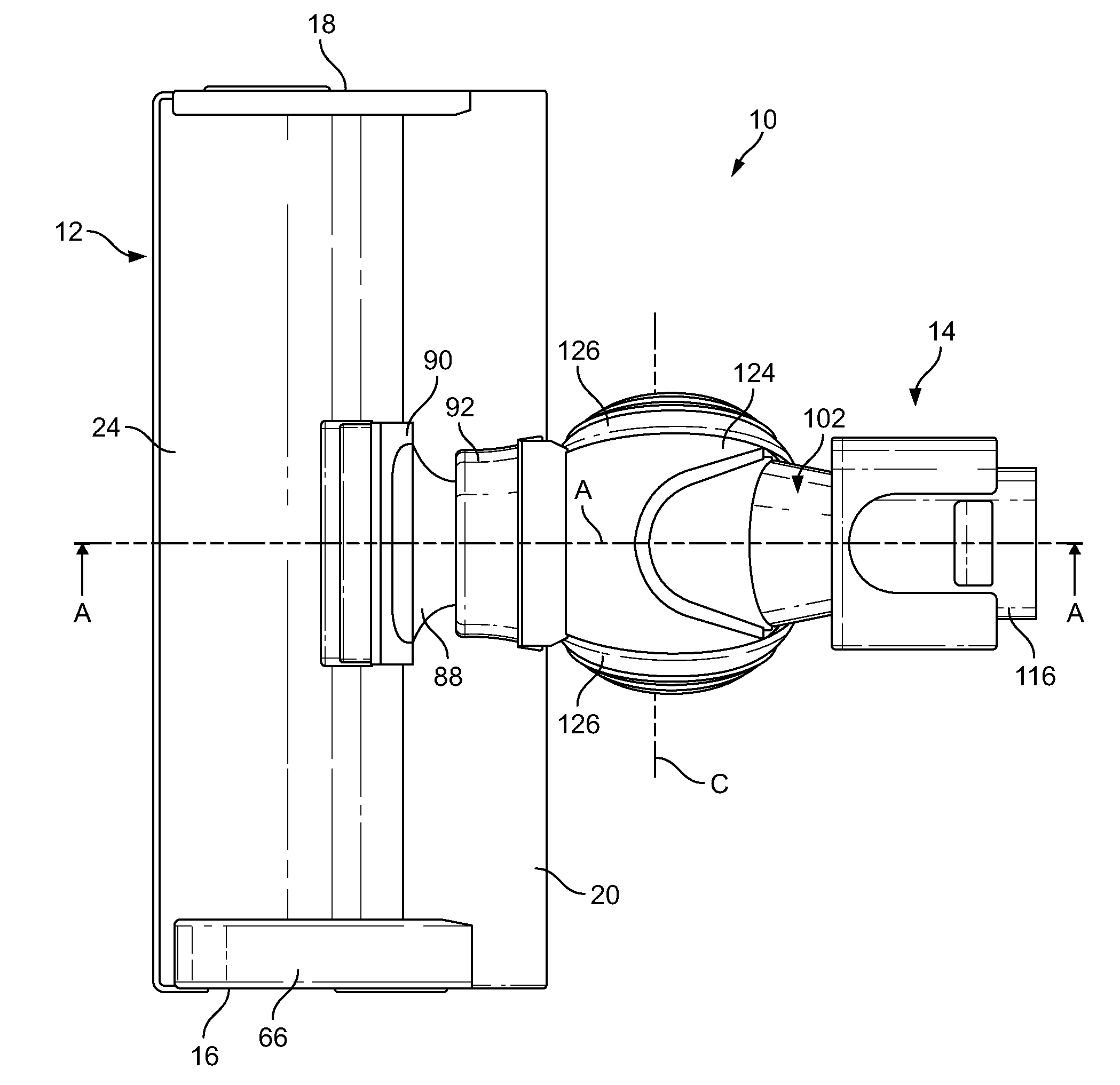
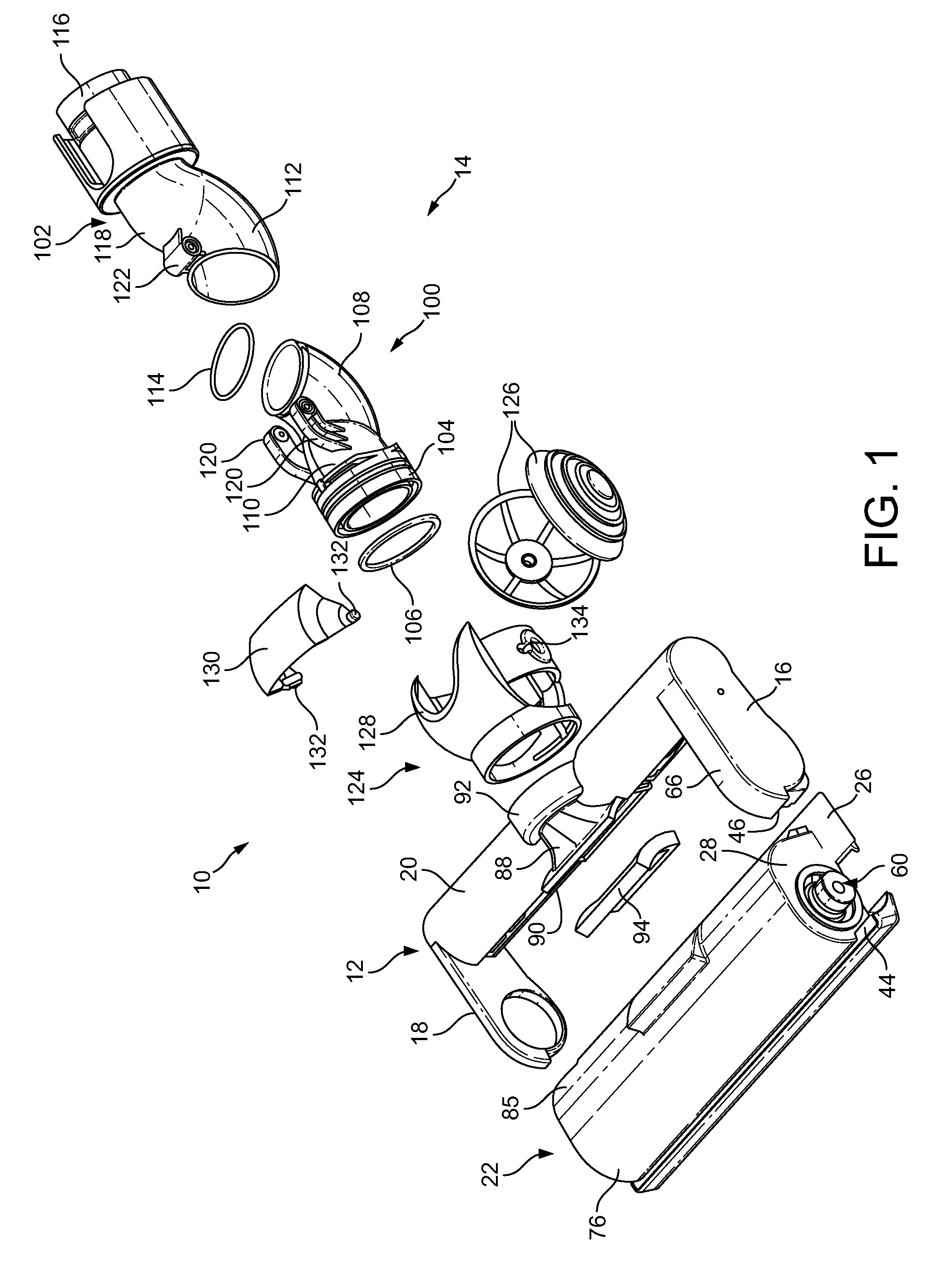
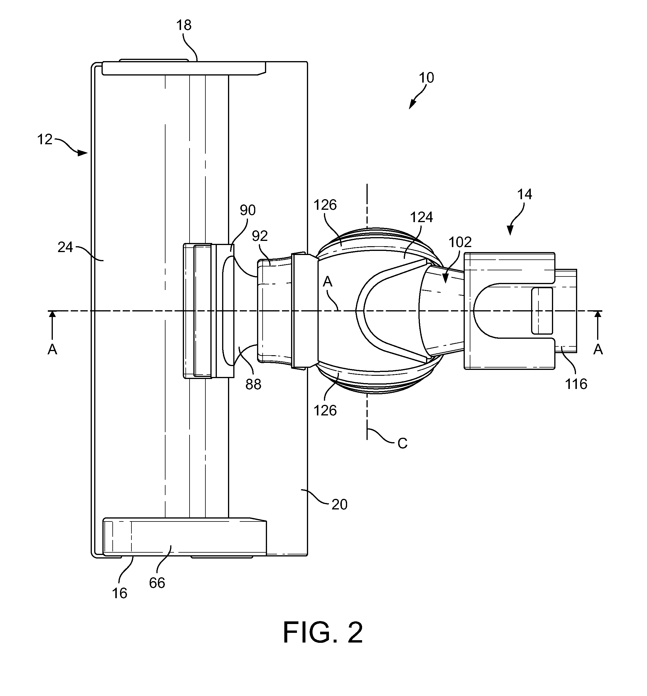
[0029]FIGS. 1 to 4 illustrate an embodiment of a cleaner head for a surface treating appliance. In this embodiment, the cleaner head 10 is arranged to be connectable to a wand or hose of a cylinder vacuum cleaning appliance. The cleaner head 10 comprises a main body 12 and a conduit assembly 14 connected to the main body 12. The main body 12 comprises substantially parallel side walls 16, 18 extending forwardly from opposite ends of a rear section 20 of the main body 12, and a moveable section 22 located between the side walls 16, 18 of the main body 12. In this embodiment the moveable section 22 is rotatably connected to the main body 12 for rotation about an axis which extends generally orthogonally between the side walls 16, 18 of the main body 12.

[0030]The moveable section 22 comprises an upper wall 24, a lower plate, or sole plate 26, and two side walls 28 which connect the sole plate 26 to the upper wall 24. The side walls 28 are located between the side walls 16, 18 of the ma...


PUM


Abstract

A cleaner head for a surface treating appliance includes a main body, a front conduit, and a rear conduit. The front conduit includes a front section connected to the main body for rotation relative thereto about a first axis extending rearwardly from the main body and centrally through the front section, a rear elbow section and at least one first connector. The rear conduit includes a front elbow section into which the rear elbow section of the front conduit is inserted, a rear section and at least one second connector connected to said at least one first connector to enable the rear conduit to pivot relative to the front conduit about a second axis which is orthogonal to the first axis and which lies outside a fluid flow path passing through the front conduit and the rear conduit.

Description

REFERENCE TO RELATED APPLICATIONS[0001]This application claims the priority of United Kingdom Application No. 1103366.9, filed Feb. 28, 2011, the entire contents of which are incorporated herein by reference.FIELD OF THE INVENTION[0002]The present invention relates to a cleaner head for a surface treating appliance. In its preferred embodiment, the present invention relates to a cleaner head for a vacuum cleaning appliance.BACKGROUND OF THE INVENTION[0003]Vacuum cleaners are generally supplied with a range of tools for dealing with specific types of cleaning. The tools include a cleaner head for general on-the-floor cleaning. The cleaner head comprises a main body which engages with a floor surface. The main body has a lower surface comprising a suction opening through which, in use, dirt and dust is drawn into the cleaner head from the floor surface.[0004]It is useful for the main body to be pivotably connected to the remainder of the cleaner head so that the suction opening can re...

Claims


Application Information

Patent Timeline
Patent Type & Authority Applications(United States)
IPC IPC(8): A47L9/00
CPCA47L9/02A47L5/36A47L9/242A47L9/04A47L9/00
Inventor MILLINGTON, DAVID ALANDIMBYLOW, STEPHEN ROBERTGAMMACK, PETER DAVID
Owner DYSON TECH LTD
Why Eureka
Try Eureka