Protective coatings and coated components comprising the protective coatings

Active Publication Date: 2012-08-30
HONEYWELL INT INC
View PDF13 Cites 8 Cited by
  • Summary
  • Abstract
  • Description
  • Claims
  • Application Information

AI Technical Summary

Benefits of technology

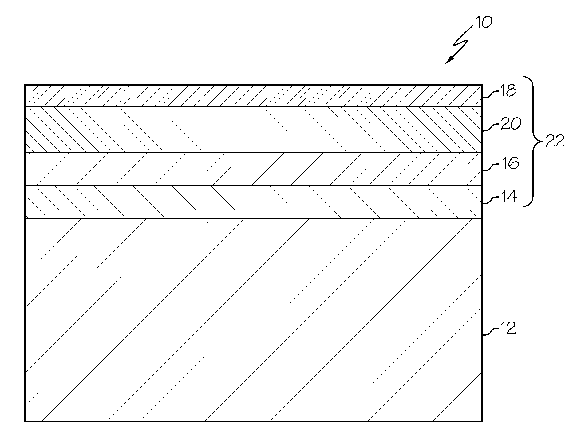
[0022]In accordance with an exemplary embodiment, metal particles may alternatively (with the plastic spheres) or additionally be added to the thermal barrier coating to increase the porosity of the TBC. The metal particles are added to compensate for the sintering effect and differences in CTE between the substrate and the protective coating. The metal particles are formed of a metal such as copper (Cu), tantalum (Ta), chromium (Cr), tungsten (W), molybdenum (Mo), and combinations thereof. The metal particles may be, for example, spherical, but other shapes may be used. The metal particles may be mixed with the ceramic material and the mixture applied overlying the EBC 16 or transition layer 20, as hereinafter described. The size of the metal particles ranges from about 20 to about 160 μm. The TBC has a thickness in the range of about 10 to about 400 μm. The mixture of the ceramic material and metal particles may be applied, for example, by plasma spraying or the like forming volatile metal oxides in the thermal barrier coating. Either during operation (flight) or during heat treatment, the volatile metal oxide particles in the TBC vaporize forming a porous TBC with a reduced coefficient of thermal expansion (CTE) relative to its CTE prior to operation or heat treatment.
[0023]In accordance with an alternative embodiment, the TBC 18 comprises a ceramic material and a metal oxide, a metal silicate, a metal disilicate, or combinations of at least two of the metal oxide, the metal silicate, and the metal disilicate. Such combinations may include a combination of a metal oxide with a metal silicate or a metal disilicate or a combination of the metal silicate with the metal disilicate. The thermal barrier coating 18 may further comprise the plastic particles. Suitable exemplary metal oxides include, for example, Yttrium oxide (Y2O3), Ytterbium oxide (Yb2O3), Scandium dioxide (Sc2O3), and combinations thereof. Suitable exemplary metal silicates include, for example, YSiO3, YbSiO3, and ScSiO3. The TBC comprises about 25 vol % of the metal oxide, the metal silicate or disilicate, or combinations of at least two of the metal oxide, the metal silicate, and the metal disilicate. The concentration of metal oxides and/or metal silicates or disilicates may be increased toward the surface of the thermal barrier coating. The presence of the metal oxide and/or silicate and/or disilicate in the TBC reduces CTE mismatch between the TBC and underlying layer(s), a

Problems solved by technology

Although silicon-based substrates have good high temperature properties and many other advantages, they may be susceptible to recession under the severe operating conditions of an operating turbine engine.
The water vapor, when mixed with silicon from the component material, forms silicon hydroxide that can result in recession of silicon from the component, reducing component service life and necessitating its replacement or repair.
Hot corrosion and erosion of the component from the salt, sulfur, and sand are also problems for substantially all substrates under severe operating conditions.
However, such intermetallic compounds have different melting points making the coating operation difficult, especially for large scale components.
The TBC is itself susceptible to degradation by various processes that occur during operation of the turbine engine.
Under severe operating conditions, built-up CMAS on engine components may melt and penetrate pores in the TBC.
As the built-up CMAS solidifies, the CMAS may cause stresses within the TBC, degrading the TBC and causing increased temperature and wear of the turbine engine components.
Additionally, other chemical processes may occur as an indirect result of CMAS build-up, further degrading the TBC and damaging engine components.
In addition, mismatched coefficients of thermal expansions (CTE) between the substrate and overlying layer(s) of the protective coating induce stress in the coating.
However, at severe operating conditions, at least a portion of the TBC may sinter, closing the pores.
The reduction in porosity results in an increase in the CTE of the TBC, hereinafter referred to as a “sintering effect.” The sintering effect can result in stress-induced fractures of the coating.

Method used


Image

  • Protective coatings and coated components comprising the protective coatings
  • Protective coatings and coated components comprising the protective coatings
  • Protective coatings and coated components comprising the protective coatings

Examples


example 1

[0026]A protective coating 22 overlying a silicon-based substrate 12 is shown in the SEM micrograph of FIG. 2. The protective coating 22 in accordance with an exemplary embodiment comprises the braze layer 14 including a high volume of intermetallic compounds 24, the EBC 16, the transition layer 20, and the TBC 18. The substrate 12 is a silicon nitride-based substrate. The braze layer 14 is silicon, 35wt % Ta and 10 wt % Cr applied as a paste to the part and brazed at about 1400° C. following standard techniques. The white particles in the braze layer are the TaSi intermetallic, gray particles are the CrSi intermetallic. The dark areas are silicon-rich. The EBC 16 is scandium disilicate. The transition layer 20 is yittria-stabilized zirconia plus tantalum oxide (white areas). The thermal barrier coating 18 is yittria-stabilized zirconia. The TBC, transition layer and EBC are applied by standard plasma spray techniques.

example 2

[0027]An exemplary protective coating 22 overlying a silicon-based substrate 12 is shown in the SEM micrograph of FIG. 3. The protective coating 22 in accordance with an exemplary embodiment comprises the braze layer 14 including a high volume of intermetallic compounds 24, the EBC 16, the transition layer 20, and the TBC 18. In FIG. 3, the substrate is a silicon nitride-based substrate. The braze layer is silicon, 20 wt % Ta and 5 wt % Cr applied as a paste to the part and brazed at about 1400° C. following standard techniques. The white particles in the braze are the TaSi intermetallic, and the gray particles are the CrSi intermetallic. The dark areas are silicon rich. The EBC is scandium disilicate. The transition layer is yittria-stabilized zirconia and tantalum oxide (white areas). The TBC is yittria-stabilized zirconia. The EBC, transition layer, and TBC were applied by standard plasma spray techniques.

example 3

[0028]An exemplary protective coating 22 overlying a silicon-based substrate 12 is shown in the SEM micrograph of FIG. 4. The protective coating 22 in accordance with an exemplary embodiment comprises the braze layer 14 including a high volume of intermetallic compounds 24, the EBC 16, the transition layer 20, and the TBC 18. In FIG. 3, the substrate is silicon nitride-based. The braze layer is silicon, 25 wt % Ta and 5 wt % Cr applied as a paste to the part and brazed at about 1400° C. following standard techniques. The white particles in the braze are the TaSi intermetallic, and the gray particles are the CrSi intermetallic. The dark areas are silicon rich. The EBC is scandium disilicate. The transition layer is yittria-stabilized zirconia and tantalum oxide (white areas). The TBC is yittria-stabilized zirconia. The EBC, transition layer, and TBC were applied by standard plasma spray techniques.

[0029]From the foregoing, it is to be appreciated that the protective coatings and coat...


PUM

PropertyMeasurementUnit
Concentrationaaaaaaaaaa
Coefficient of linear thermal expansionaaaaaaaaaa
Melt temperatureaaaaaaaaaa

Abstract

A coated component is provided comprising a silicon-based substrate and a braze layer overlying the silicon-based substrate. The braze layer comprises silicon, tantalum, and a metal element having substantially the same melt temperature with silicon as tantalum has with silicon. The braze layer further comprises ceramic particles. Protective coatings are also provided.

Description

STATEMENT REGARDING FEDERALLY SPONSORED RESEARCH OR DEVELOPMENT[0001]This invention was made with Government support under W911W6-08-2-0001 awarded by U.S. Army. The Government has certain rights in this invention.TECHNICAL FIELD[0002]The present invention generally relates to protective coatings for turbine engine components that operate under severe operating conditions, and more particularly relates to protective coatings and coated components comprising the protective coatings.BACKGROUND[0003]Turbine engines are used as the primary power source for various kinds of aircraft. Silicon-based substrates, such as silicon nitride and silicon carbide composites, are used for making turbine engine components that may be exposed to severe operating conditions. As used herein, “severe operating conditions” include high gas velocities (greater than about 500 m / second, exposure to salt, sulfur, and sand, and high temperatures of up to about 1500° C.). Although silicon-based substrates have ...

Claims


Application Information

Patent Timeline
IPC IPC(8): B32B27/06C09D1/00
CPCC04B41/009Y02T50/672C04B41/89F01D5/288F05D2230/90F05D2300/222Y02T50/67C04B41/52C23C28/042C04B35/565C04B35/806C04B35/584C04B41/4539C04B41/5096C04B41/5133C04B41/4527C04B41/5024C04B41/5027C04B41/5042Y02T50/60
InventorRAYBOULD, DEREKCHIPKO, PAULTUCKER, BRADLEY REED
OwnerHONEYWELL INT INC