
Modular and non-modular cortical buttress device

a cortical buttress and module technology, applied in the field of fixing devices, can solve the problems of destroying the connection between a typical bone plate and a fractured clavicle, affecting the repair efficiency of the bone screw,

Inactive Publication Date: 2012-09-06
TOBY ORTHOPAEDICS
View PDF9 Cites 40 Cited by
  • Summary
  • Abstract
  • Description
  • Claims
  • Application Information

AI Technical Summary

Problems solved by technology

Fractures of bones such as the clavicle can be difficult to repair.
Such deforming forces can destroy the connection between a typical bone plate and the fractured clavicle.
However, the cortex bone is relatively thin, and thus, the threads of the bone screws have a limited amount of bone to engage.
That is, the superior and inferior cortex bone provide limited purchase for the threads of the bone screws.
Thus, when subjected to the deforming forces, the limited amount of engagement of the bone screws afforded with the cortex bone can lead to failure of the connection between the bone plate and the fractured clavicle.

Method used


Image

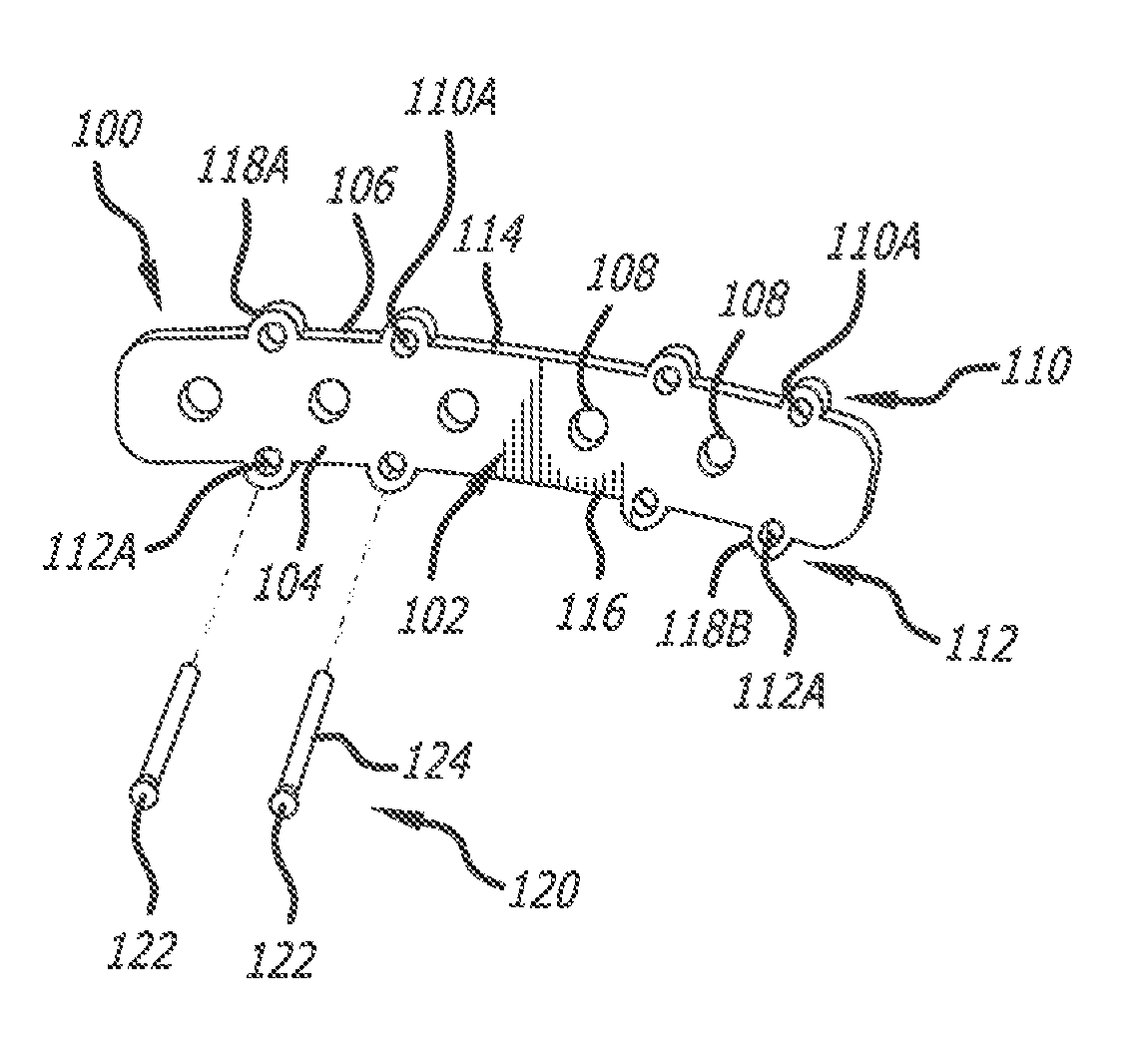
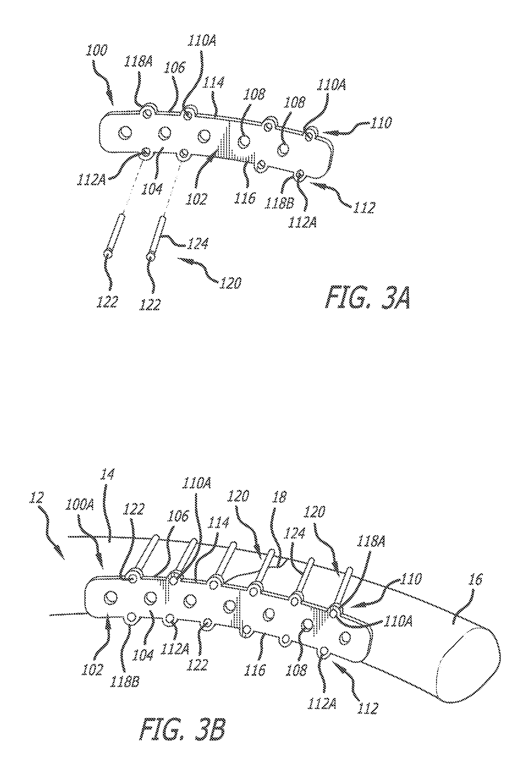
  • Modular and non-modular cortical buttress device
  • Modular and non-modular cortical buttress device
  • Modular and non-modular cortical buttress device

Examples


Embodiment Construction

[0026]The following description is intended to be representative only and not limiting, and many variations can be anticipated according to these teachings. Reference will now be made in detail to the preferred embodiments of this invention, examples of which are illustrated in the accompanying drawings.

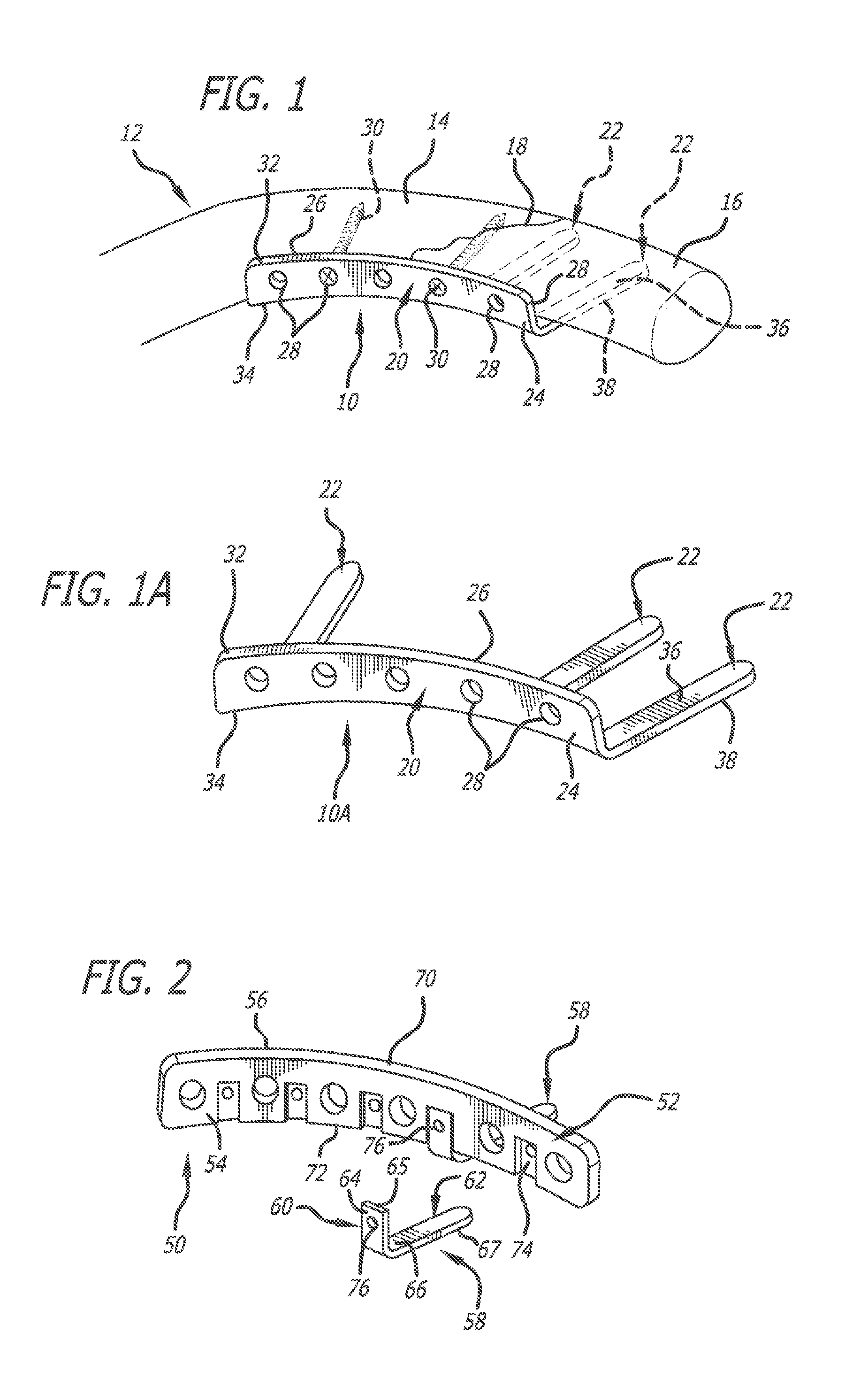
[0027]One preferred embodiment of a fixation device of the present invention is generally indicated by the numeral 10 in FIG. 1. Fixation device 10 is formed as a bone plate 11, and is used in stabilizing a fractured clavicle 12. Fractured clavicle 12 includes a first portion 14, a second portion 16, and a fracture line 18 along which first and second portions 14 and 16 are separated. By stabilizing first and second portions 14 and 16 with respect to one another, fixation device 10 serves to facilitate reduction and repair thereof.

[0028]Fixation device 10 includes a body portion 20 for bridging first and second portions 14 and 16, and various tines 22 extending outwardly from body po...


PUM


Abstract

A fixation device serves in facilitating reduction and repair of a fractured bone such as a clavicle or a pelvis. The fixation device includes a bone plate adapted to overlie and contact bone fragments of a fractured bone. The bone plate can include tines extending outwardly from the edge thereof to contact the exterior of and support the bone fragments.

Description

[0001]The present application claims the benefit of provisional Application No. 61 / 448,739, filed Mar. 3, 2011; which is incorporated by reference herein.BACKGROUND OF THE INVENTION[0002]1. Field of the Invention[0003]The present invention generally relates to a fixation device used to facilitate reduction and repair of a fractured bone. More particularly, the present invention relates to a bone plate that counteracts deformation forces from surrounding tissue. More specifically, the present invention relates to a bone plate that is configured to maintain the connection of the bone plate with the portions of a fractured bone.[0004]2. Description of the Prior Art[0005]Fractures of bones such as the clavicle can be difficult to repair. Portions of the fractured clavicle are pulled in opposing directions by the interaction thereof with surrounding tissue. For example, deforming forces are applied to the fractured clavicle in at least two directions: (1) force from muscle traction super...

Claims


Application Information

Patent Timeline
Patent Type & Authority Applications(United States)
IPC IPC(8): A61B17/80
CPCA61B17/8061A61B17/8066A61B17/80A61B17/866A61B17/8085
Inventor GONZALEZ-HERNANDEZ, EDUARDO
Owner TOBY ORTHOPAEDICS
Learn More