Push button-type switch device

a switch device and push button technology, applied in the direction of emergency contacts, contact mechanisms, electrical devices, etc., can solve the problem of unfavorable clicks, and achieve the effect of good clicks

Inactive Publication Date: 2012-09-13
FUJITSU COMPONENENT LTD
View PDF9 Cites 13 Cited by
  • Summary
  • Abstract
  • Description
  • Claims
  • Application Information

AI Technical Summary

Benefits of technology

[0007]According to the present invention, the direction in which the operable member moves upon being pushed is limited so as to allow the operable member to move in a fixed orientation. Therefore, the actuating member between the base portion and the operable member can be elastically deformed uniformly in the circumferential direction to produce a good click when being pushed.

Problems solved by technology

This results in non-uniformity in the deformation of the skirt portion in the circumferential direction, and a favorable click may not be obtained.

Method used


Image

  • Push button-type switch device
  • Push button-type switch device
  • Push button-type switch device

Examples


Embodiment Construction

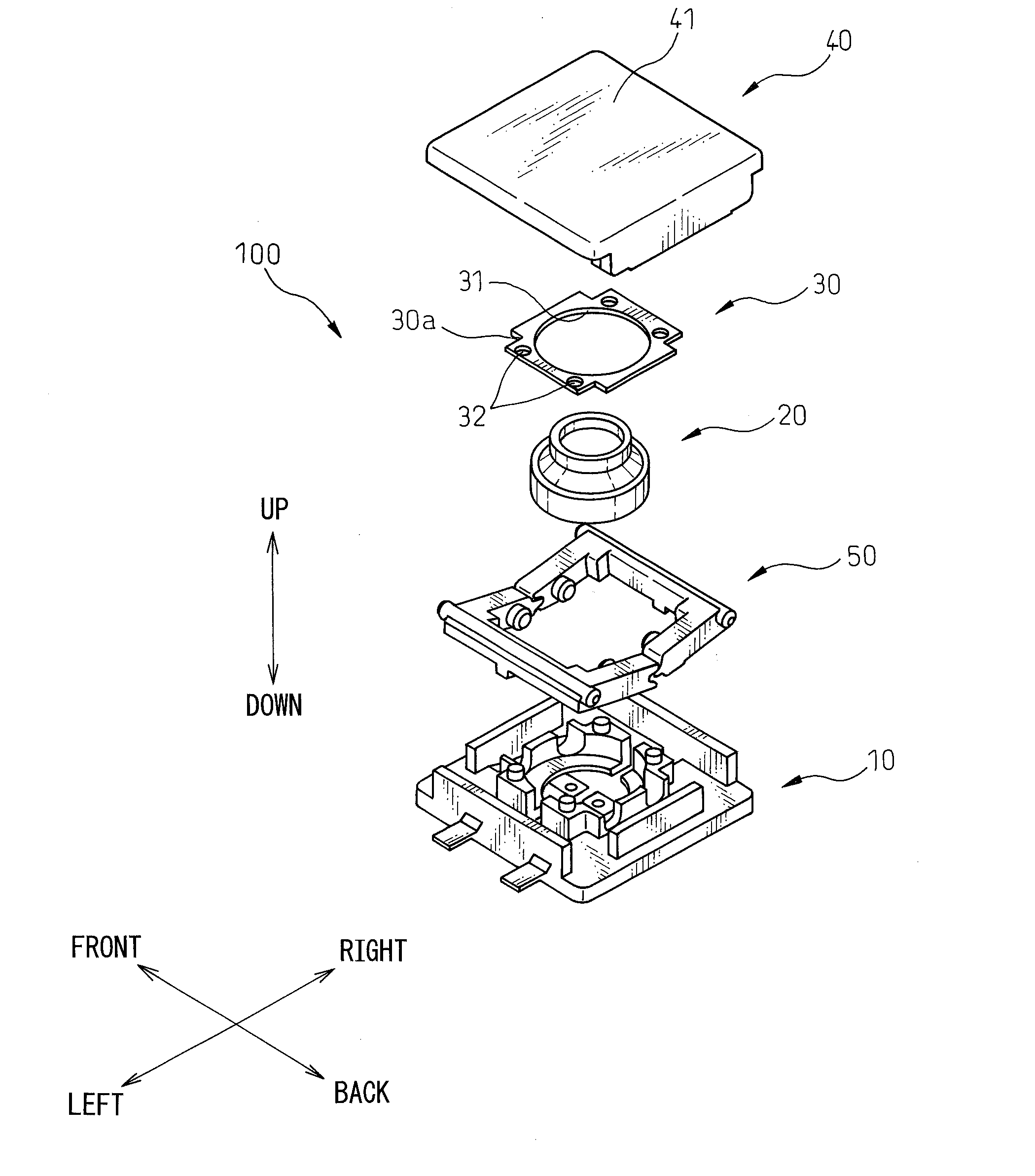
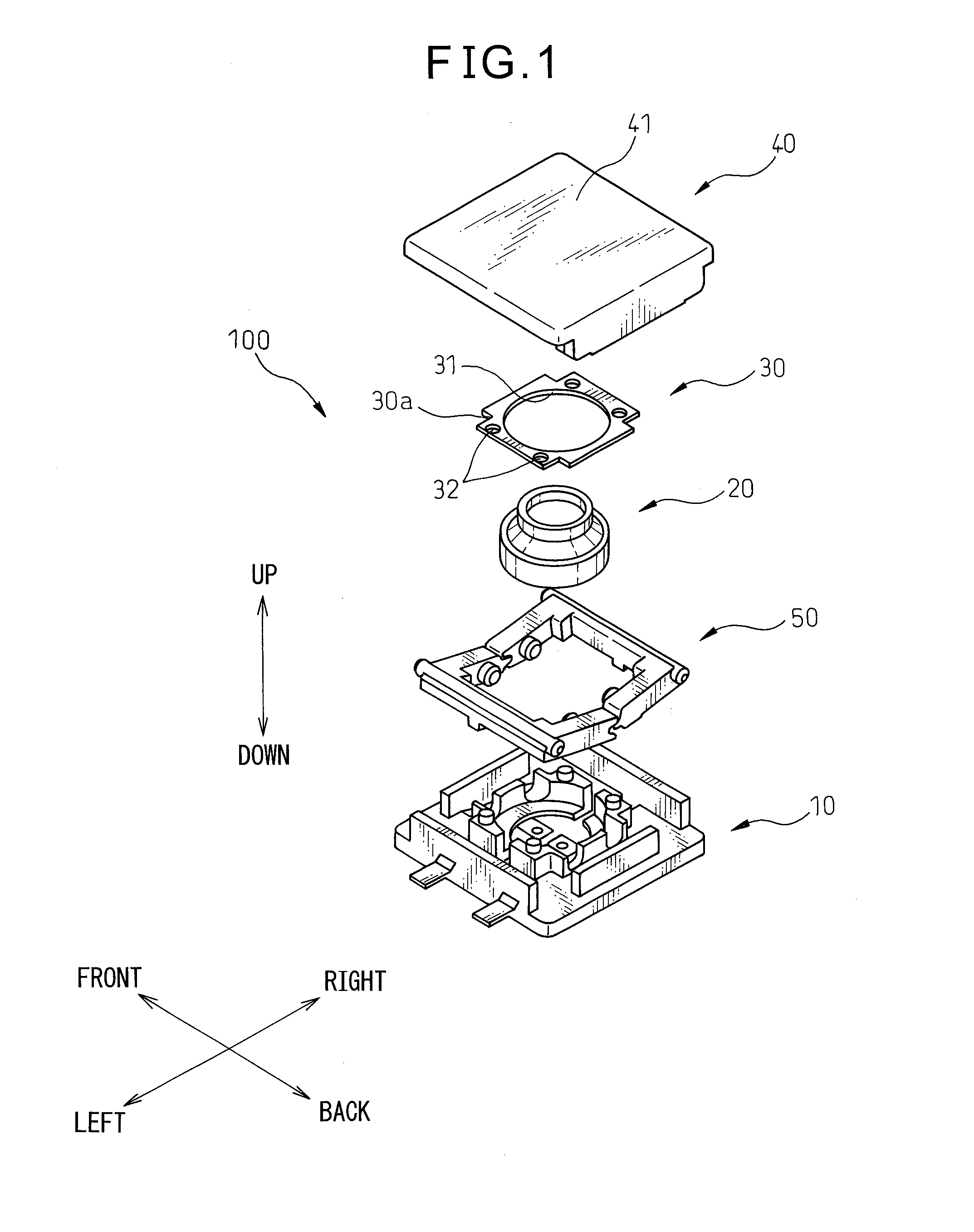
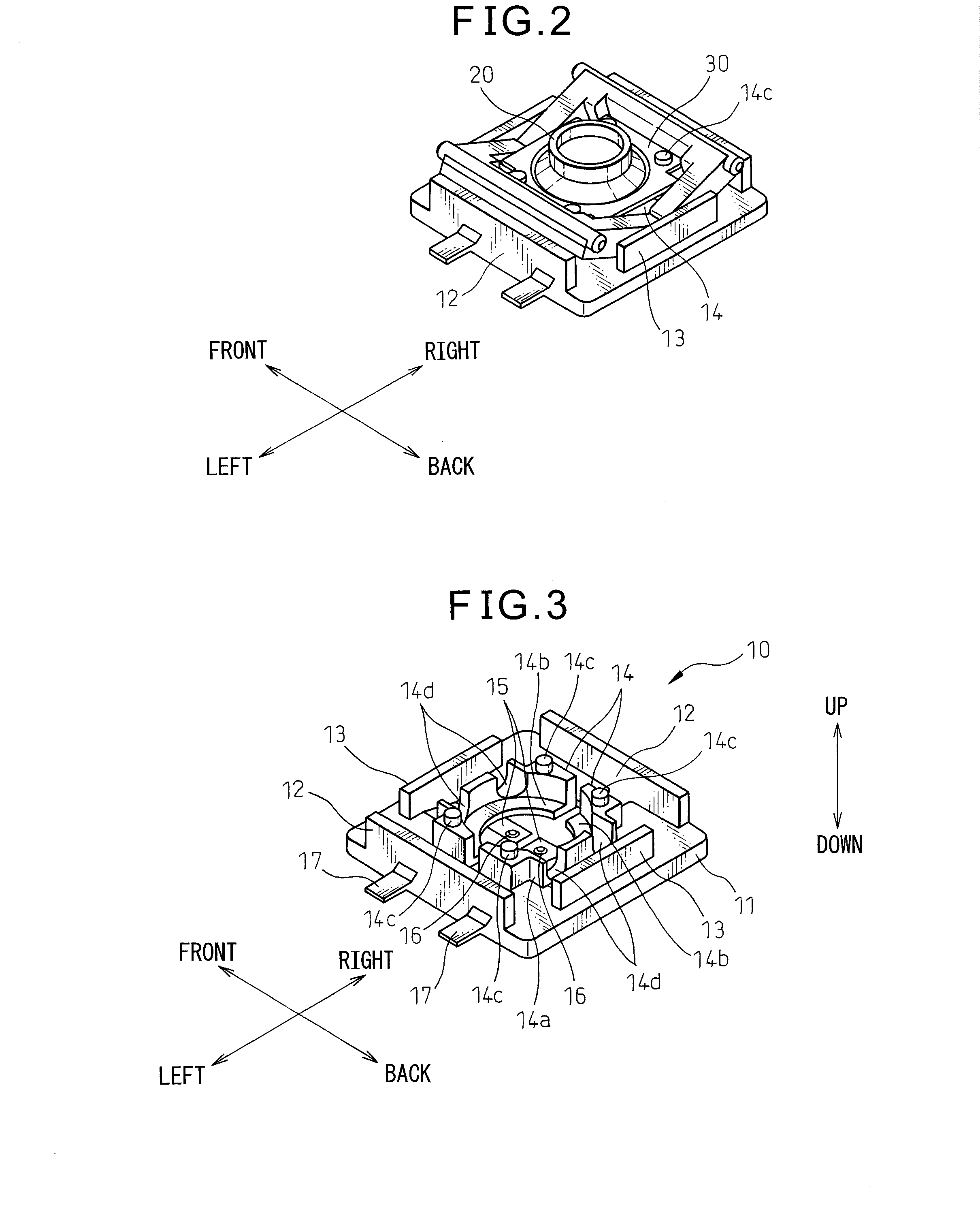
[0029]A push button-type switch device according to one embodiment of the invention will now be described. FIG. 1 is an exploded perspective view illustrating an overall constitution of the push button-type switch device 100 according to the embodiment of the present invention. FIG. 2 is a perspective view of the push button-type switch device 100 in an assembled state. In FIG. 2, a key top 40 is not shown. In the following description for convenience, the up-and-down direction, front-and-back direction and right-and-left direction are defined as shown in the figures, and a constitution of each portion will be described according to these definitions.

[0030]The push button-type switch device 100 includes a base portion 10, an actuating member 20 placed on an upper surface of the base portion 10, a cover 30 attached to the base portion 10 with the actuating member 20 provided therebetween, a key top 40 that is to be pushed downward in operation, and a pair of right and left link membe...


PUM


Abstract

A push button-type switch device includes a pair of fixed contacts, an operable member to be pushed, an actuating member elastically deformable upon the operable member being pushed, a movable contact which short-circuits the pair of fixed contacts due to elastic deformation of the actuating member, and a limiting part arranged to limit a direction in which the operable member moves and making the operable member move in a fixed orientation. The limiting part includes a pair of link members that engage with each other, one ends of the link members rotatably supported by the base portion, and the other ends thereof slidably supported by the operable member. This produces a good click irrespective of a position where the operable member is operated.

Description

BACKGROUND OF THE INVENTION[0001]1. Field of the Invention[0002]This invention relates to a push button-type switch device used for a variety of electronic equipment.[0003]2. Description of the Related Art[0004]There has heretofore been known a push button-type switch device having a key top supported via a skirt portion which is made of an elastic material (see, for example, JP-A-9-120741). According to the switch device described in JP-A-9-120741, a pair of fixed contacts are arranged on a surface of a circuit board, while a movable contact is arranged on an inner lower surface of the key top, and the key top is operated to elastically deform the skirt portion, so as to provide a unique operability with click feeling when the movable contact comes into contact with the fixed contacts.[0005]In the device described in JP-A-9-120741, however, if the key top has, for example, an oval shape, upon pushing an end of the key top, the key top becomes tilted and the pushing force acts in an...

Claims


Application Information

Patent Timeline
Patent Type & Authority Applications(United States)
IPC IPC(8): H01H13/36H01H13/02H01H13/14
CPCH01H3/125H01H2203/038H01H13/36H01H2237/00H01H13/14H01H2215/012
Inventor FUNAKOSHI, KATSUYANAKAMURA, SHUJINISHINO, TAKESHIMARUYAMA, JUNICHIKOIKE, TAMOTSU
Owner FUJITSU COMPONENENT LTD
Why Eureka
Try Eureka