Moveable step for assisting entry into vehicles

a technology of moving steps and vehicles, applied in the direction of vehicle components, steps arrangement, supplementary fittings, etc., can solve the problems of visually disrupting the clean line and streamlined appearance of the bar, the height of the entry into the passenger compartment, and the required “step” is too high to permit easy entry, etc., to achieve the effect of easy lowering

Active Publication Date: 2012-09-13
N FAB INC
View PDF17 Cites 41 Cited by
  • Summary
  • Abstract
  • Description
  • Claims
  • Application Information

AI Technical Summary

Benefits of technology

The technical effect of this patent is to create a new design for vehicles that makes it easier to get inside, provides extra space at the bottom of the car, looks good on top of other cars, helps people enter more efficiently, offers protection against damage to the sides of the vehicle, allows for easy adjustability of steps to various levels, and improves overall mobility for passengers.

Problems solved by technology

The technical problem addressed in this patent is the difficulty for individuals to enter vehicles with high road clearance, due to the high floor of the passenger cab. Existing side bars with steps are often too high off the ground, aesthetically displeasing, and do not provide a stable step closer to the ground. The invention provides a solution by allowing for vertical movement of a step that is variably affixed to the side bar, providing a stable step closer to the ground and maintaining the appearance of the side bar.

Method used


Image

  • Moveable step for assisting entry into vehicles
  • Moveable step for assisting entry into vehicles
  • Moveable step for assisting entry into vehicles

Examples


Embodiment Construction

[0032]Detailed descriptions of the preferred embodiments are provided herein. It is to be understood, however, that the present invention may be embodied in various forms. Various aspects of the invention may be inverted, or changed in reference to specific part shape and detail, part location, or part composition. Therefore, specific details disclosed herein are not to be interpreted as limiting, but rather as a basis for the claims and as a representative basis for teaching one skilled in the art to employ the present invention in virtually any appropriately detailed system, structure or manner.

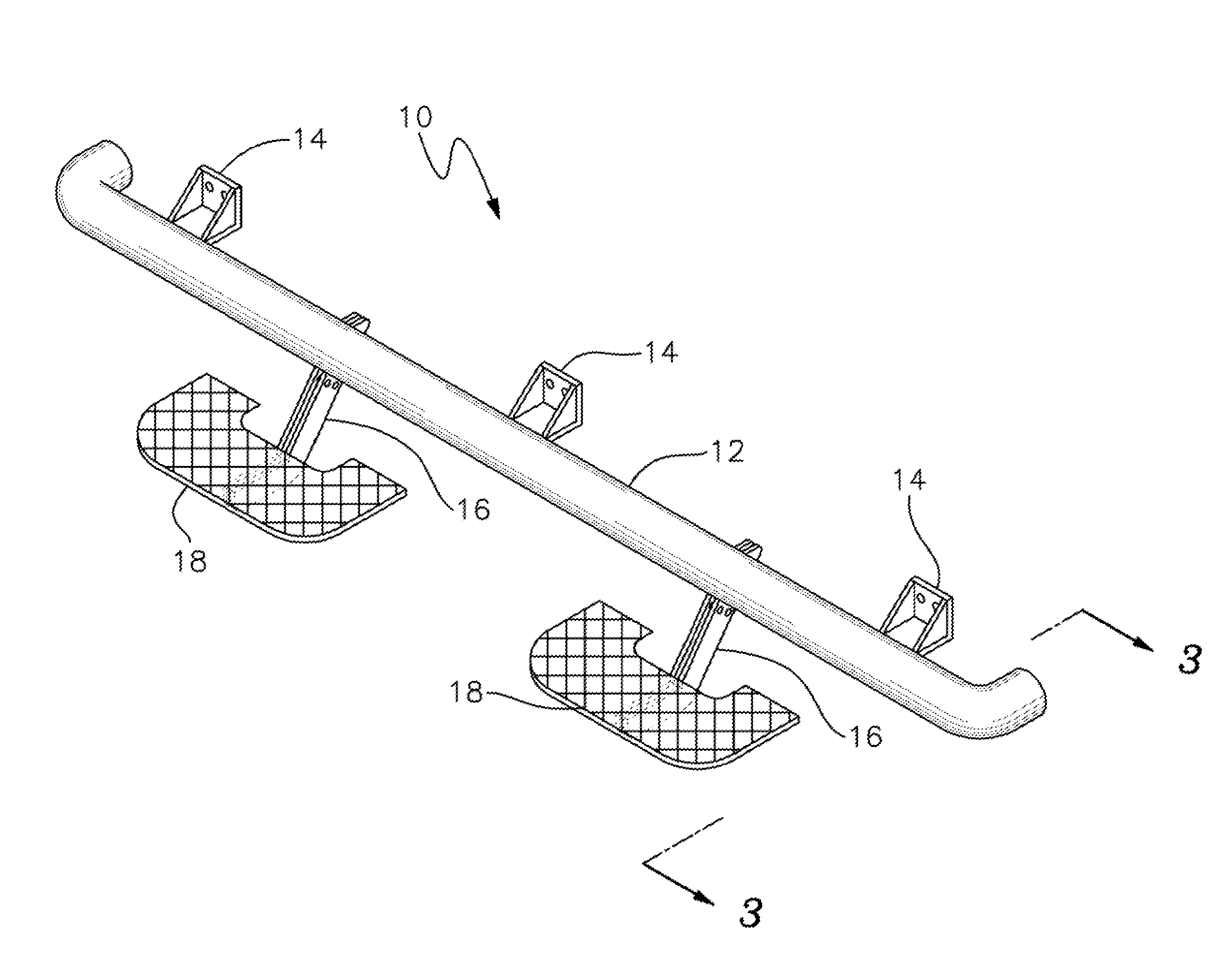
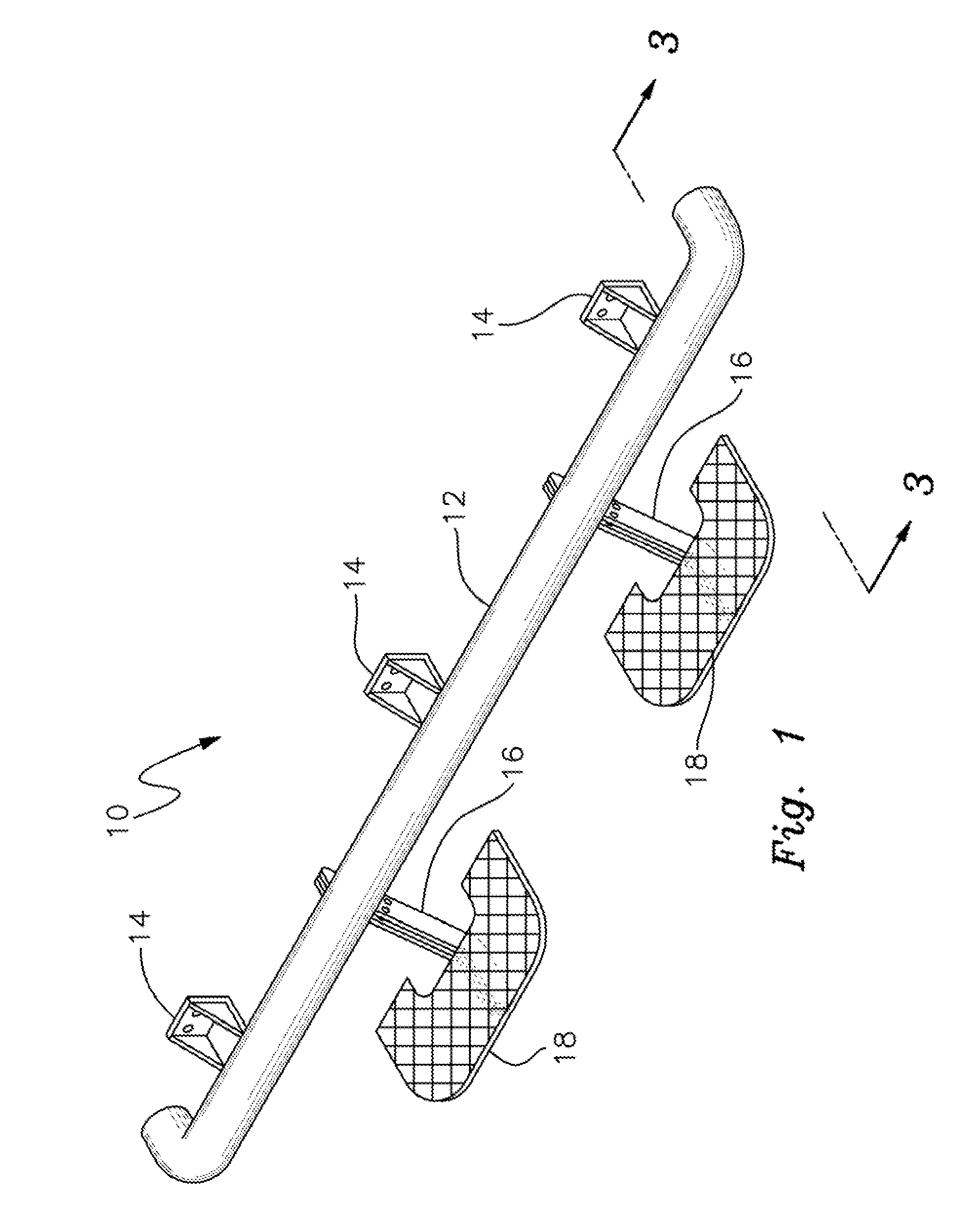
[0033]FIG. 1 shows a perspective view of a side bar and step assembly configuration 10 according to a preferred embodiment of the invention. Side bar 12 may be affixed to the chassis of the vehicle through a variety of conventional means including bolts, welding, brazing, or other bracketing. Side bar 12 may be an elongate member of any of a variety of generally cylindrical shapes having a ...


PUM


Abstract

A side bar and steps attached to the side bar attached to a vehicle or to the side of the vehicle by welds, brazing, or bolting to brackets welded to the side bar or vehicle. A step is constructed by attaching a curved or flat member to the top of an L-shaped support bar that is in turn connected to the side bar or vehicle. The steps are movably affixed to a tab that is welded to the side bar or vehicle. The L-shaped supports have a plurality of engagement points so that the step can be adjusted upward and downward using the different attachment points. In this manner steps can be moved for different users depending on the height of the vehicle or user preference. The L-shaped support bars may be flared outward and provided with a plate for mounting the step thereon.

Description


Claims


Application Information

Patent Timeline
Owner N FAB INC
Why Eureka
Try Eureka