Heater with flame display

a technology of flame display and heater, which is applied in the field of heaters, can solve the problems of not visually altering, displaying, and displaying the fire or flame, and the flame in these devices typically does not provide significant heat to the surrounding area, and the flame in these devices does not form a dramatic visual flame

Active Publication Date: 2018-10-16
WET ENTERPRISES
View PDF31 Cites 8 Cited by
  • Summary
  • Abstract
  • Description
  • Claims
  • Application Information

AI Technical Summary

Benefits of technology

[0031]In this manner, the heater of the current invention may provide a dramatic aesthetic effect that conveys mood and / or complements the surrounding area.
[0053]In another aspect of the invention, the heater provides a pleasing overall design appearance and aesthetic effect. To this end, the heater of the current invention preferably has a sleek appearance that may evoke an appearance of art or fine furniture. The heater may also aesthetically complement the surrounding furniture and / or motif of its location. The aesthetic effect of the heater may also be enhanced by the dramatic and variable fire display referenced above.

Problems solved by technology

However, these types of heaters typically do not visually alter, feature, or display the fire or flame.
And while heating devices that display an actual or simulated flame may exist, the flame in these devices typically does not provide significant heat to the surrounding area.
The flame in these devices does not form a dramatic visual flame effect, and usually looks like a mere pilot light.
In addition, these existing devices do not efficiently provide heat laterally to the surrounding area because most of the heat is radiated upward through and around the top portion of the device.
The heat therefore rises or otherwise dissipates without efficiently heating the area below.
As such, existing devices used by restaurants in outdoor areas only heat the areas immediately surrounding the device, in an inefficient manner.
It is common to see several such heaters grouped together, because individually, they do not provide significant heat near the ground where the people are standing or seated.
Other types of existing devices may include artificial or simulated flames, but these devices do not use an actual flame with combustion providing heat.
As another example, simulated flames have been used in architectural elements such as with indoor or outdoor torches, but these devices are intended to provide only the visual effect of flame, and do not provide significant heat for warming the surrounding area.
This device emits some heat to the surrounding area, but the heat is extracted from a hot water source, and not produced by combustion from an actual flame or fire.
However, the artificial flame in this device does not provide heat by combustion.
However, the visual effect of the flame provided by these devices is limited.
Furthermore, these devices are not designed to emit significant amounts of heat for efficiently warming a surrounding area.
As such, these devices generally do not warm the surrounding area laterally, as most of the heat travels upward.
This method of heat distribution is inefficient given that hot air rises, and heat released from the top of a device will quickly dissipate in relation to the area below which is typically the area that needs to be heated.
Beyond the foregoing, the flame element in existing architecturally-oriented devices typically consists of flames that are relatively static in appearance and cannot be customized.
Accordingly, the visual display provided by existing devices is limited.
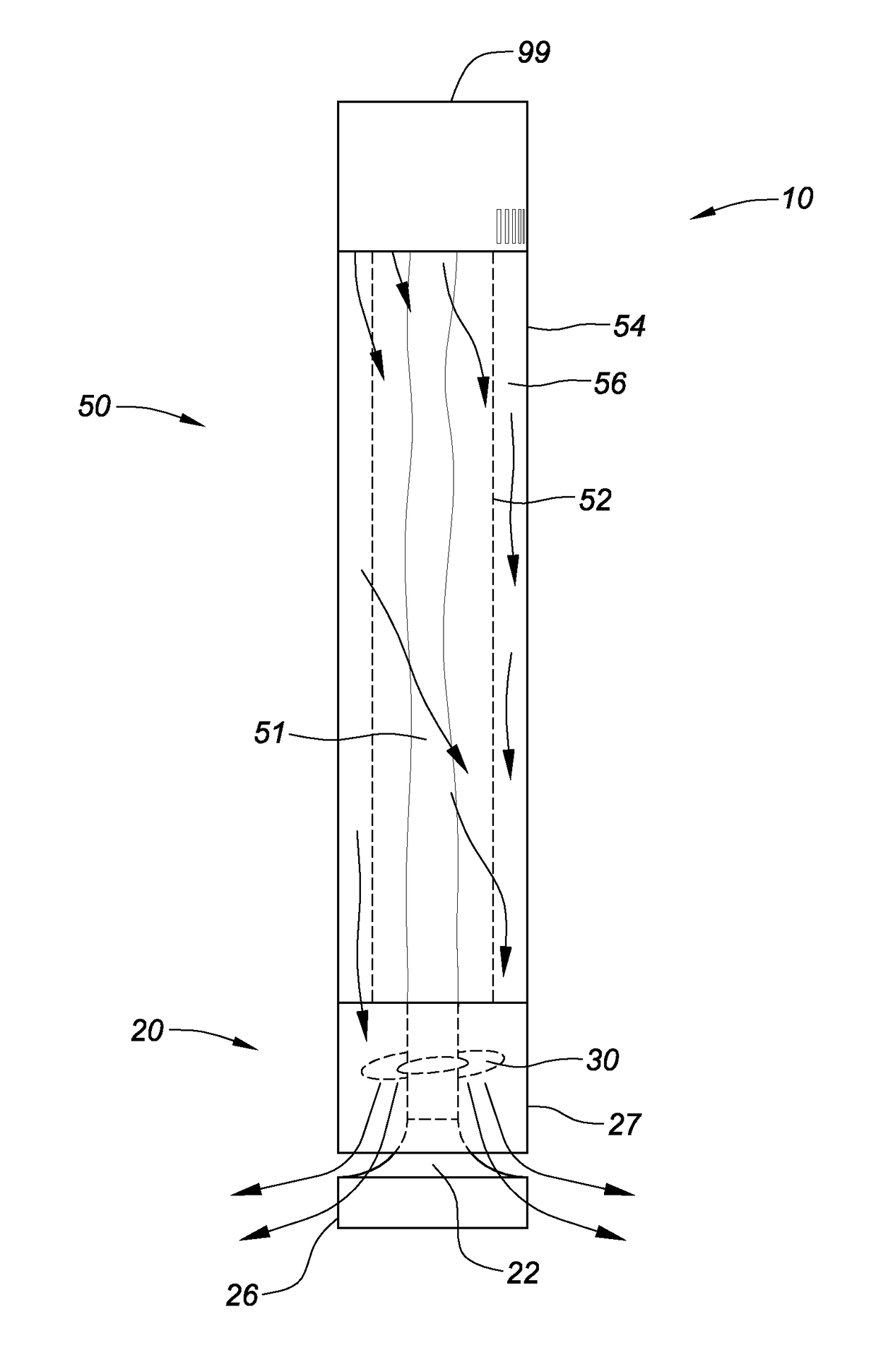
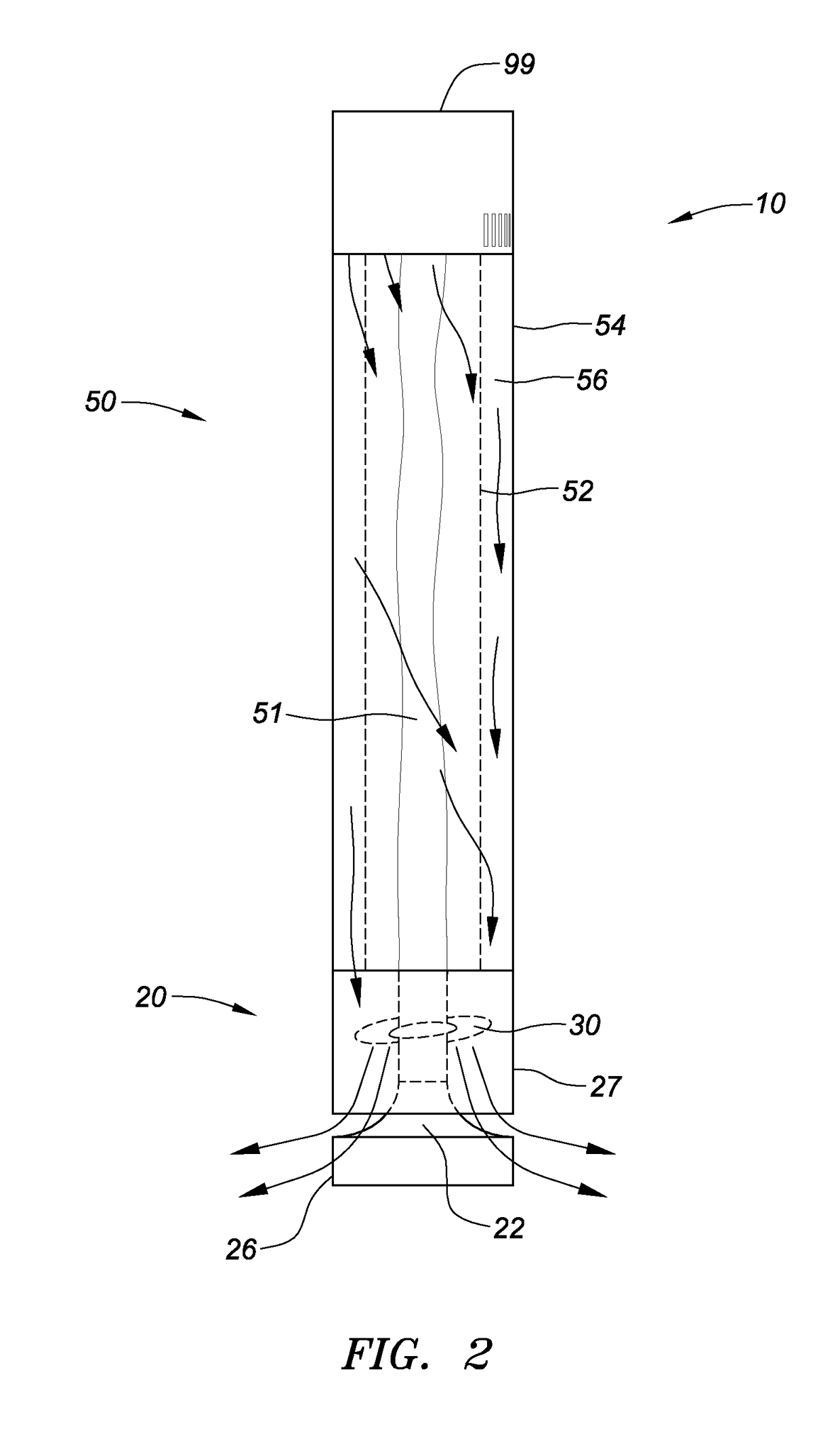
While some existing devices may allow the appearance of the flame to be altered somewhat, these devices typically still do not use vortex flame to provide a dramatic and customizable display or to efficiently heat the surrounding area.
However, the vortex flame in that device is designed to save fuel, and is not for purposes of providing a visual display.
In addition, this system is not designed to heat the surrounding area, or to recapture the updraft of the heat and redirect it to ground level for efficient distribution.
Similarly, CN103196159A, entitled “Grading Trapped Vortex Annular Combustor” discloses a vortex in high power gas turbines to increase combustion efficiency, but this device does not efficiently distribute heat to the surrounding area, while also providing a visual flame display.
U.S. Pat. No. 7,097,448 to Chesney, entitled “Vortex Type Gas Lamp,” uses a flame element designed to provide light to a room, but the flame therein is not used to efficiently heat the surrounding area.
However, such heaters do not include any visible flame element.
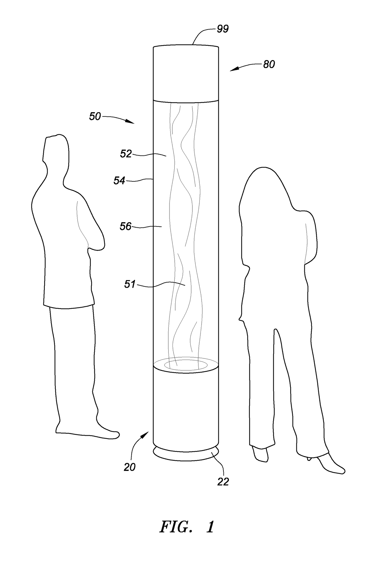
Beyond the lack of a heater device that efficiently provides heat and also provides a flame display, there are other drawbacks to existing heater devices.
For example, heater devices that are mounted to the ground are not portable.
Even existing portable devices may include electric cords for power that may be hazardous when lying on the ground, especially in crowded areas like restaurants.
Furthermore, many existing heaters may become dirty or damaged after repeated use due to fumes and heat byproducts or misuse.
Many of these heaters are difficult to clean or repair and are oftentimes continued to be used in restaurants and other locations despite their dirty and / or scratched and dented appearance.
Many existing heaters may also be difficult to start or operate, and may involve components that break or are unreliable.
This increases cost and maintenance or may result in the heater not being used.
The longstanding need for heaters that provide significant heat is confirmed by the fact that existing heaters are used, albeit inefficiently to heat various locations.
However, the inadequacy of these types of heaters to provide heat is confirmed by the fact that oftentimes, several of these heaters are lined up next to each other because they individually do not provide much heat.
And as noted above, these flames do not provide much heat.

Method used


Image

  • Heater with flame display
  • Heater with flame display
  • Heater with flame display

Examples


Embodiment Construction

[0102]Preferred embodiments of heater 10 of the current invention and related items are now described. In general, heater 10 may efficiently provide heat to warm a surrounding area and also provide a visual feature of a flame, such as a flame or fire vortex or expression. In this manner, heater 10 may uniquely serve both the utilitarian function of providing heat, as well as the aesthetic function of providing a dynamic visual display that enhances its location. As discussed in more detail below, the overall design of heater 10 itself may also be aesthetically unique and significant.

[0103]It is preferred that heater 10 provides a significant amount of heat to warm various types of surrounding areas such as rooms, apartments, other housing or business locations, outdoor locations and other areas. It is also preferred that the heat provided by heater 10 may be varied in intensity and the direction(s) at which heat is provided to suit different areas to be heated. Similarly, the flame ...


PUM


Abstract

A heater with a visual flame display is described. The heater may include a top portion and a base, separated by concentric cylinders. The innermost cylinder houses a flame element, which may be spun into a vortex. The cylinders may be constructed from transparent materials such that the flame element is visible to an observer. The base provides heat at or near ground level for efficient heat distribution.

Description

CROSS REFERENCE TO RELATED APPLICATIONS[0001]This application claims the benefit of U.S. Provisional Application No. 61 / 010,431, filed Jun. 10, 2014, the contents of which are incorporated herein by reference.FIELD OF THE INVENTION[0002]The present invention generally relates to heaters, including heaters that may warm a surrounding area and provide a visual flame display, as well as heaters that provide an overall aesthetic effect.BACKGROUND OF THE INVENTION[0003]Various types of heaters that provide heat extracted from fire or flame have existed for some time. These types of heaters include gas-burning devices. However, these types of heaters typically do not visually alter, feature, or display the fire or flame. And while heating devices that display an actual or simulated flame may exist, the flame in these devices typically does not provide significant heat to the surrounding area.[0004]For example, existing outdoor or patio heaters typically include a top section which houses ...

Claims


Application Information

Patent Timeline
Patent Type & Authority Patents(United States)
IPC IPC(8): F24C15/00F24C3/00F24C1/14F24H3/02F24H9/00F24C15/06
CPCF24C15/002F24C1/14F24C3/002F24H9/0068F24C15/06Y02B40/166F24H3/025F24H3/065F24H9/02F24H9/2085F24C3/022F24C3/04F24C3/082F24C15/006Y02B40/00F24H15/35F24H15/305F24H9/25F24H15/281
Inventor FULLER, MARKFULLER, SUSANMOLNAR, DEZSODOYLE, JAMES W.YOO, RIAEWINSLOW, SCOTT
Owner WET ENTERPRISES
Why Eureka
Try Eureka