
Table

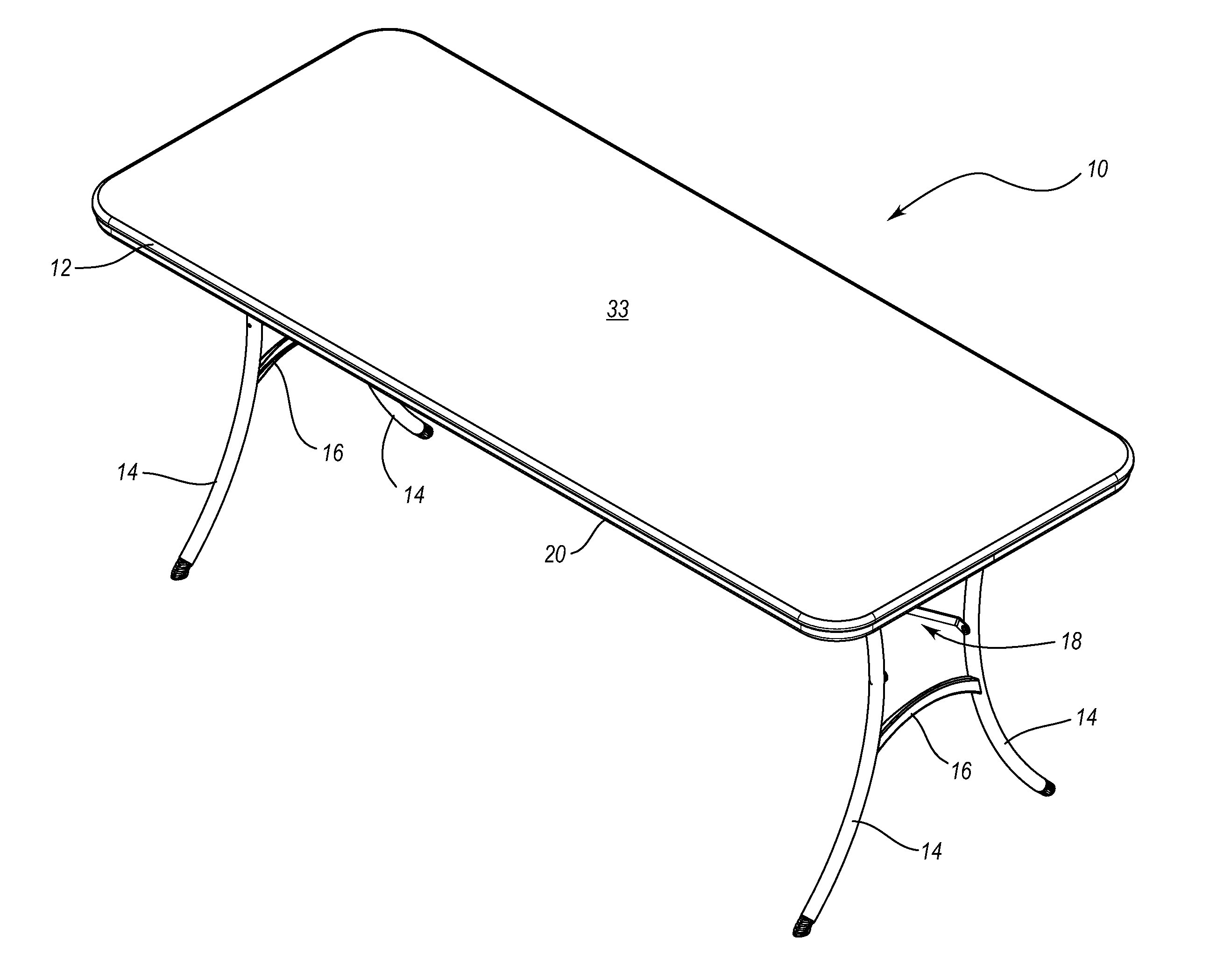
a technology for tables and chairs, applied in the field of tables, can solve the problems of awkward or difficult to move the table, and the conventional table tops constructed from wood or metal are also relatively expensive, so as to facilitate stacking and/or nesting of the tables, improve aesthetics and appearance, and facilitate the connection to the table.

Inactive Publication Date: 2007-03-15
LIFETIME PRODUCTS
View PDF51 Cites 2 Cited by
  • Summary
  • Abstract
  • Description
  • Claims
  • Application Information

AI Technical Summary

Benefits of technology

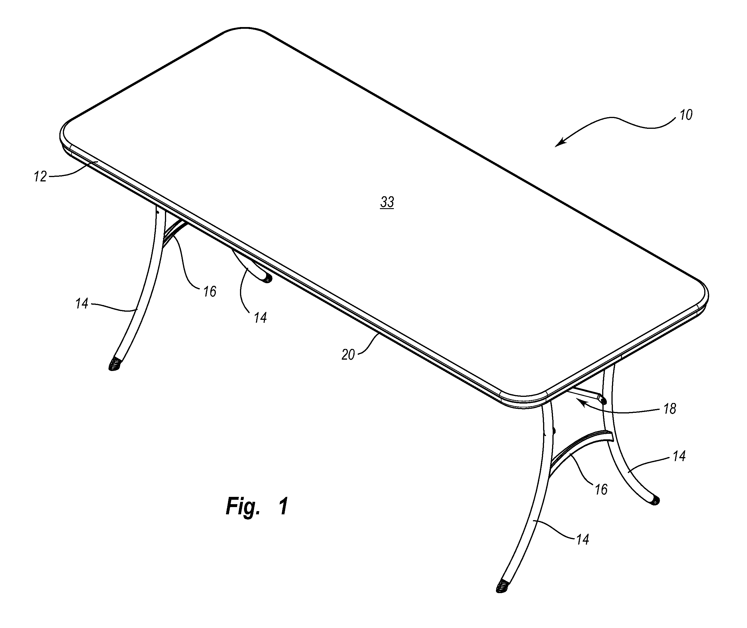
[0008] One aspect is a table that may be relatively lightweight, which may allow the table to be more easily transported and moved. For example, the table may include a lightweight table top that reduces the overall weight of the table. The table may also include a lightweight frame that is connected to and may support the table top. In addition, the table may include lightweight legs that support the table top above a surface such as the ground or a floor. Significantly, if the table includes a lightweight table top, frame and legs, then a lightweight table to be constructed. Of course, a relatively lightweight table may be constructed with a lightweight table top, frame and / or legs, as desired.
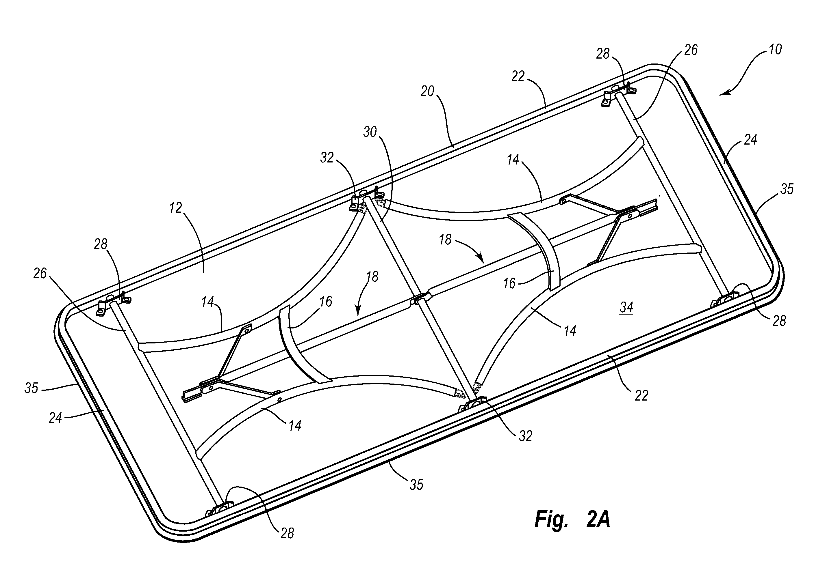
[0021] Another aspect is the table may include components that can be quickly and easily manufactured. For example, the lower portion of the table top may have a generally planar construction, which may simplify the manufacturing process and allow the table top to be quickly and easily manufactured. In addition, the legs and / or frame may be quickly and easily attached to the table top, which may reduce manufacturing costs.

Problems solved by technology

Table tops constructed from wood, particle board or metal, however, are often relatively heavy and this may make the table awkward or difficult to move.
Conventional table tops constructed from wood or metal are also relatively expensive and the table tops must generally be treated or finished before use.
In addition, these relatively heavy table tops may increase the cost of transportation, shipping and storage of the tables.

Method used


Image

  • Table
  • Table
  • Table

Examples


Embodiment Construction

[0007] A need therefore exists for a table that eliminates the above-described and / or other disadvantages and problems.

[0008] One aspect is a table that may be relatively lightweight, which may allow the table to be more easily transported and moved. For example, the table may include a lightweight table top that reduces the overall weight of the table. The table may also include a lightweight frame that is connected to and may support the table top. In addition, the table may include lightweight legs that support the table top above a surface such as the ground or a floor. Significantly, if the table includes a lightweight table top, frame and legs, then a lightweight table to be constructed. Of course, a relatively lightweight table may be constructed with a lightweight table top, frame and / or legs, as desired.

[0009] Another aspect is a table that may includes legs which are movable between a use position and a storage position. The legs preferably extend outwardly from the tabl...


PUM


Abstract

A table may include a table top, a frame and one or more support members such as legs. Advantageously, the table top may include a generally planar upper surface and a generally planar lower surface. In particular, the lower surface of the table top may be substantially free of any downwardly extending projections such as a lip. Desirably, the table includes a frame and at least a portion of the frame is exposed and visible when the table is being used. In addition, the table may include one or more guard members that are sized and configured to protect portions of the table, such as the corners. Significantly, the guard members may be selectively connected to the table top or the frame, which may allow the guard members to be repaired or replaced.

Description

CROSS-REFERENCE TO RELATED APPLICATIONS [0001] This application is a continuation of U.S. patent application Ser. No. 10 / 949,777, filed on Sep. 24, 2004, entitled TABLE. U.S. patent application Ser. No. 10 / 949,777 claims the benefit of and priority to U.S. Provisional Patent Application Ser. No. 60 / 513,161, filed Oct. 20, 2003, entitled TABLE. U.S. patent application Ser. No. 10 / 949,777 is a continuation-in-part of U.S. Design patent application Ser. No. 29 / 192,259, filed Oct. 20, 2003, entitled TABLE TOP WITH EXPOSED PORTIONS OF THE FRAME. Each of these disclosures are incorporated by reference in their entireties.BACKGROUND OF THE INVENTION [0002] 1. Field of the Invention [0003] The present invention generally relates to furniture and, in particular, to tables. [0004] 2. Description of Related Art [0005] Conventional tables are used for a variety of purposes and come in a wide array of designs. Conventional tables often include table tops constructed from wood, particle board or ...

Claims


Application Information

Patent Timeline
Patent Type & Authority Applications(United States)
IPC IPC(8): A47B3/00A47B3/08A47B13/02A47B13/08
CPCA47B3/0912Y10S108/901
Inventor WINTER, DAVID C.ASTLE, ROBERT A.NYE, S. CURTISASHBY, KENTSTRONG, L. CURTIS
Owner LIFETIME PRODUCTS
Learn More