
Annular wheel-trim for vehicle floating-seat rim flange, and assembly made up of an annular wheel-trim and of an adapter for a floating-seat wheel

Active Publication Date: 2019-10-03
MICHELIN & CO CIE GEN DES ESTAB MICHELIN
View PDF0 Cites 3 Cited by
  • Summary
  • Abstract
  • Description
  • Claims
  • Application Information

AI Technical Summary

Benefits of technology

The patent text describes a new invention that improves the appearance of wheels on vehicles by using an elastic extender between the rim and the wheel. The invention allows the wheel to look like a rigid wheel by harmonizing the colors, such as with light alloy wheels. Additionally, the invention includes a flexible hubcap that allows for a certain amount of deformation based on the design of the rim. This results in a more visually appealing wheel.

Problems solved by technology

And especially when the space able to accommodate this travel is great.
There then arises the problem of finding the technical means of achieving a visual perception of a large-diameter wheel, extending as far as the tyre bead.

Method used


Image

  • Annular wheel-trim for vehicle floating-seat rim flange, and assembly made up of an annular wheel-trim and of an adapter for a floating-seat wheel
  • Annular wheel-trim for vehicle floating-seat rim flange, and assembly made up of an annular wheel-trim and of an adapter for a floating-seat wheel
  • Annular wheel-trim for vehicle floating-seat rim flange, and assembly made up of an annular wheel-trim and of an adapter for a floating-seat wheel

Examples


Embodiment Construction

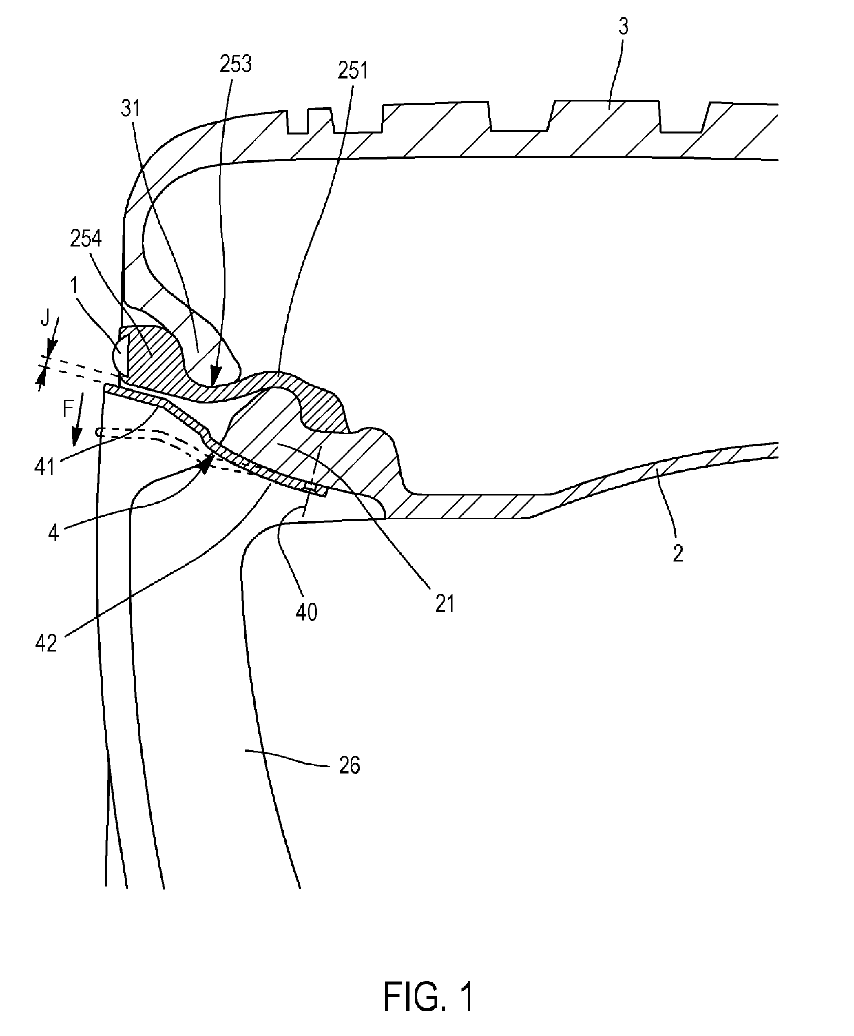
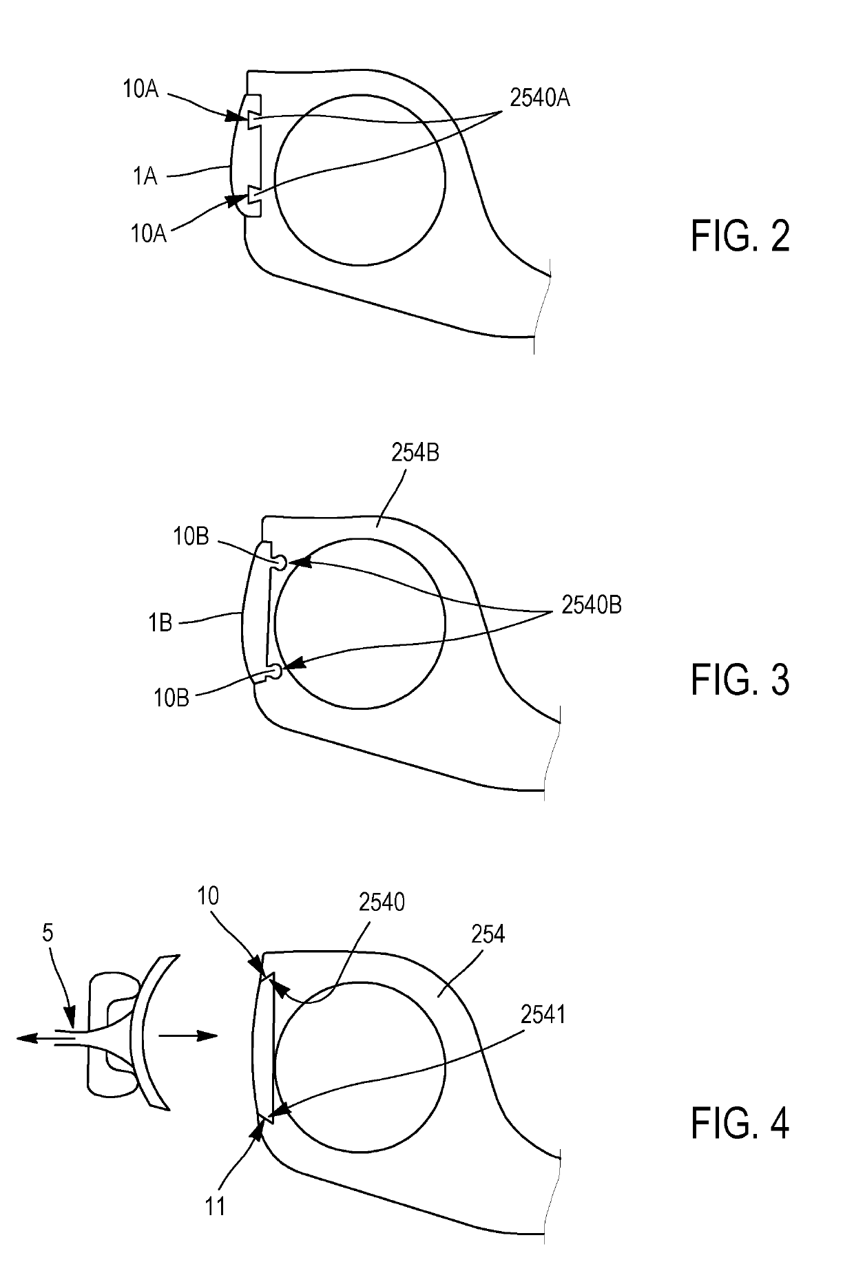
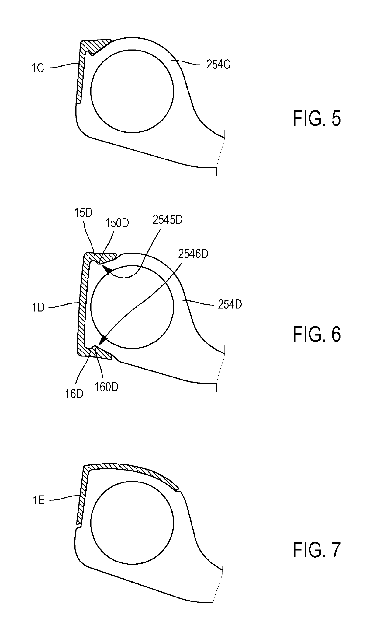
[0018]FIG. 1 shows an annular wheel-trim 1, a floating-seat wheel 2, a tyre 3 and a hubcap 4. The floating-seat wheel 2 is formed by the assembly of a rigid wheel base 21, generally made in one piece, and two rim lateral parts 251, both flexible. Each rim lateral part comprises a tyre seat 253 extended axially outwards by a flange 254. The tyre 3 comprises two beads 31 each one mounted on one of the said tyre seats 253. In this embodiment, each of the rim lateral parts readopts identical teaching to the extender in document WO2016 / 046197; each rim lateral part is made of reinforced elastomer that allows it to move F in a radial direction of the flange 254 with respect to the opposite end of the said rim lateral part.

[0019]As an alternative, the floating-seat wheel may also comprise flexible rim lateral parts mounted in various ways, such as, for example, according to one or another of the examples given in document WO2015 / 086662, in all aspects equivalent as far as the present inven...


PUM


Abstract

An annular wheel-trim 1 for a wheel 2 that has a floating tyre seat 2, comprising rim lateral parts 251, each rim lateral part comprising a tyre seat 253 extended axially outwards by a flange 254, comprises fixing elements able to provide removable attachment to the flange 254.

Description

FIELD OF THE INVENTION[0001]The subject of the invention is an annular wheel-trim for the flange of a wheel of which the seat intended to accept the tyre bead is radially floating and extended by a flange.[0002]A tyre, a rim, an extender, an annular wheel-trim, which are products discussed in the present invention, are objects which are usually described by a representation in a meridian plane, namely a plane containing an axis of rotation, the axis of rotation of the tyre. The radial and axial directions respectively denote the directions perpendicular to the axis of rotation of the tyre and parallel to the axis of rotation of the tyre. In what follows, the expressions “radially” and “axially” respectively mean “in a radial direction”, and “in the axial direction”. The expressions “radially on the inside” or, respectively, “radially on the outside” mean “closer to” or, respectively, “further away from, the axis of rotation of the tyre, in a radial direction”. A meridian plane is a ...

Claims


Application Information

Patent Timeline
IPC IPC(8): B60B7/01B60B7/06B60B7/08B60C15/02
CPCB60B2900/572B60C15/0209B60B7/063B60B7/08B60B7/01
Inventor WALSER, DANIEL
Owner MICHELIN & CO CIE GEN DES ESTAB MICHELIN
Learn More