Vapor delivery devices and methods

a technology of vapor delivery device and liquid, which is applied in the direction of lighting and heating apparatus, heating types, separation processes, etc., can solve the problems of liquid being subject to contamination, adulteration and/or evaporation, and variations in the dose of vapor delivered,

Active Publication Date: 2012-09-13
CQENS TECH INC
View PDF4 Cites 111 Cited by
  • Summary
  • Abstract
  • Description
  • Claims
  • Application Information

AI Technical Summary

Benefits of technology

[0003]In one aspect, a vapor delivery device may have a vaporizing element and an electrical power source in a housing. A switch controls supply of electrical power to the vaporizing element from the electrical power source. A tube connects a liquid reservoir to the vaporizing element. A first valve, a second valve, and a pump are generally associated with the tube. A lever pivotally supported on or in the housing may be positioned to operate the first valve, the second valve, the pump and the switch, via pivoting movement of the lever. Other and further objects and advantages will become apparent from the following detailed description, which provides examples of embodiments of the invention. Persons of ordinary skill will readily be led to other additional examples of the invention that are not specifically described here, but are still intended to be within the scope of the invention.

Problems solved by technology

Still, disadvantages remain in the design and performance of vaporizing devices.
These include variations in the dose of vapor delivered and leakage or performance failures unless the vaporizing device is maintained in an upright position during use, or during the packaging, shipping and storage of the device.
In addition, with some vaporizing devices, the liquid may be subject to contamination, adulteration and / or evaporation under certain conditions.

Method used


Image

  • Vapor delivery devices and methods
  • Vapor delivery devices and methods
  • Vapor delivery devices and methods

Examples


Embodiment Construction

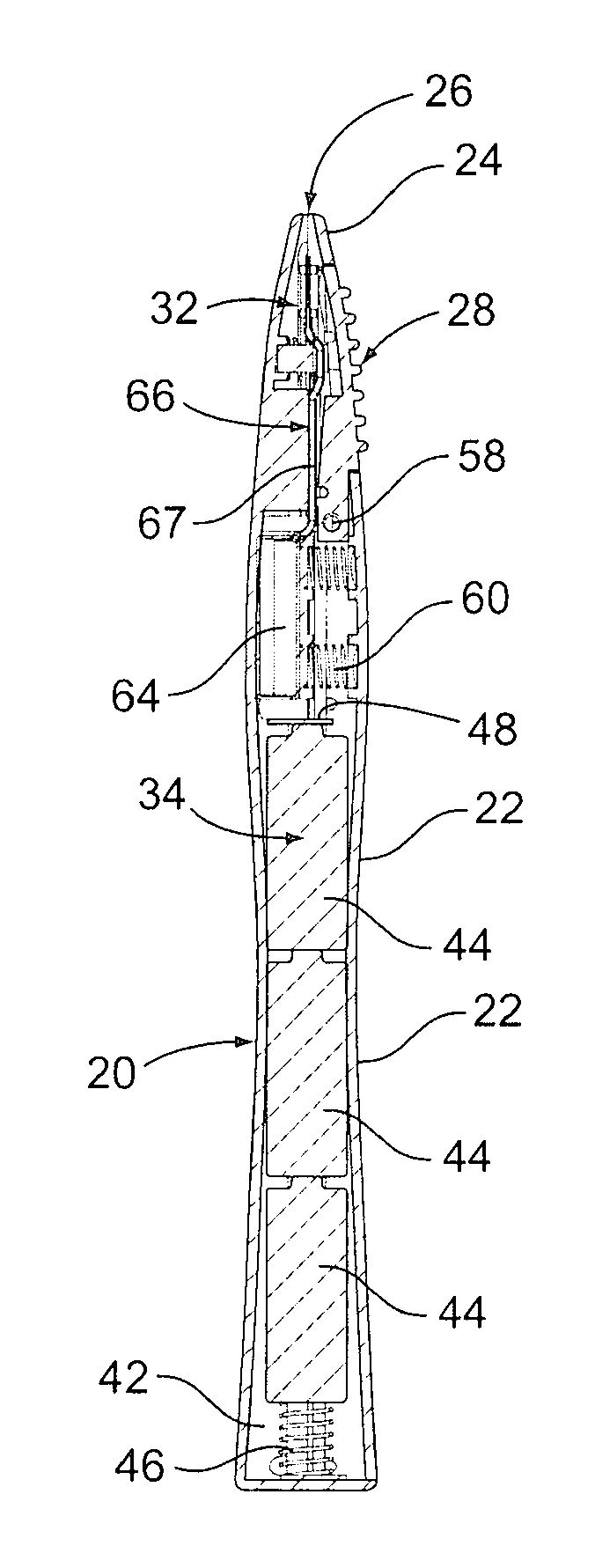
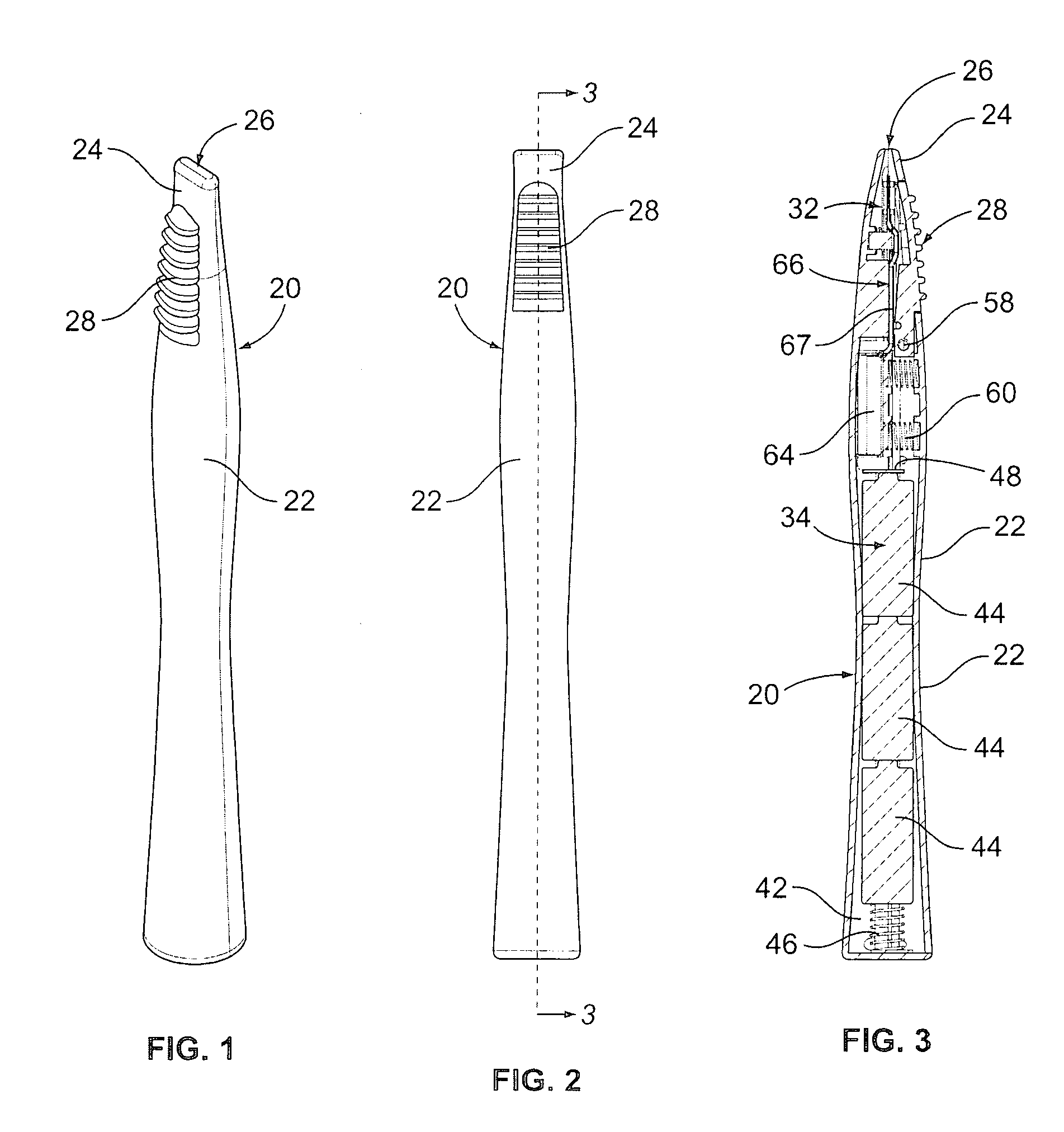
[0022]Turning now in detail to the drawings, as shown in FIGS. 1 and 2, a vaporizing device 20 has an elongated housing 22 with a mouthpiece 24 and a lever 28 adjacent to a back or top end of the housing. A mouthpiece opening 26 extends into the mouthpiece 24. Referring further to FIGS. 3-5, the device 20 includes a liquid delivery system 30 and a vaporizing system 32, as well as an electrical power system 34. The electrical power system 34 may include batteries 44 within a battery compartment 42 of the housing 22, and with the batteries electrically connected to a flexible circuit board 82 via a spring 46 and contacts 48. As shown in FIG. 5, the housing may be provided with left and right sides, in a clamshell design. The lever 28 may be attached to the housing 22 at a pivot 58.

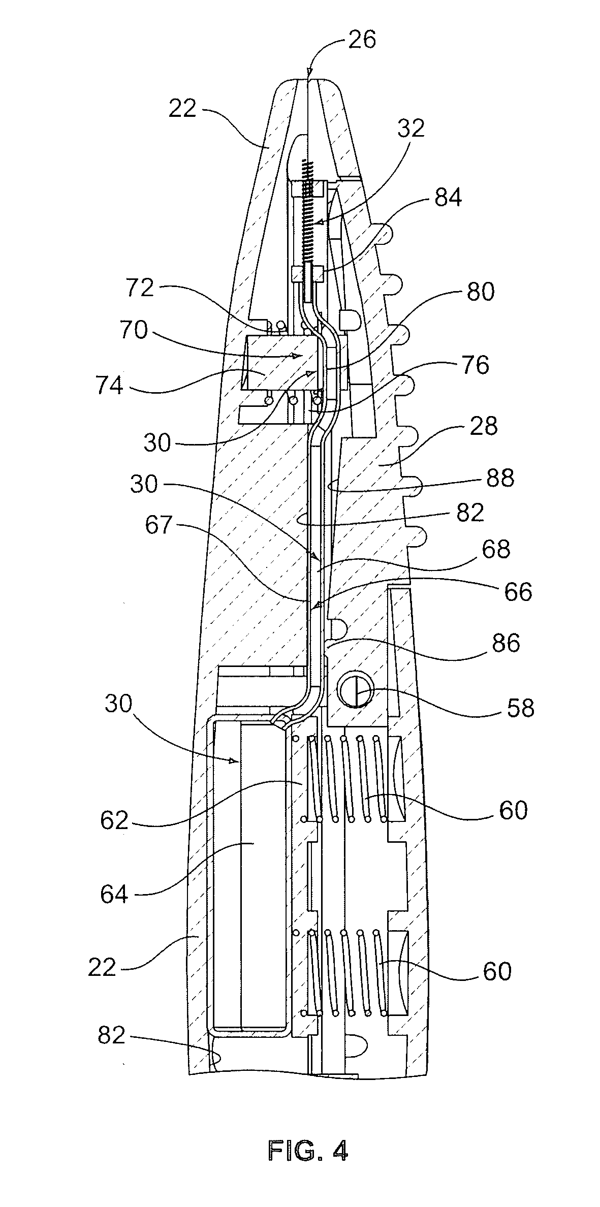
[0023]As shown in FIG. 4, the liquid delivery system 30, in the example shown, includes a resilient or flex wall liquid chamber or reservoir 64 connected via a tube 66 to a lever valve 70. The reservoir 20 m...


PUM


Abstract

In a vapor delivery device, a carrier or an expedient for an active ingredient is a liquid that can be vaporized by exposure to a concentrated, focused heating point using an efficient electrical power source. The device may have a vaporizing element and an electrical power source in a housing. A switch controls supply of electrical power to the vaporizing element from the electrical power source. A tube connects a liquid reservoir to the vaporizing element. A first valve, a second valve, and a pump are generally associated with the tube. A lever pivotally supported on or in the housing may be positioned to operate the first valve, the second valve, the pump and the switch, via pivoting movement of the lever. The device efficiently provides a uniform dose of vapor with each actuation.

Description

BACKGROUND OF THE INVENTION[0001]The field of the invention is vaporizing a liquid for inhalation. Various vaporizing devices have been used in the past. Still, disadvantages remain in the design and performance of vaporizing devices. These include variations in the dose of vapor delivered and leakage or performance failures unless the vaporizing device is maintained in an upright position during use, or during the packaging, shipping and storage of the device. In addition, with some vaporizing devices, the liquid may be subject to contamination, adulteration and / or evaporation under certain conditions.[0002]Accordingly, it is an object of the invention to provide an improved vapor delivery system.SUMMARY OF THE INVENTION[0003]In one aspect, a vapor delivery device may have a vaporizing element and an electrical power source in a housing. A switch controls supply of electrical power to the vaporizing element from the electrical power source. A tube connects a liquid reservoir to the...

Claims


Application Information

Patent Timeline
Patent Type & Authority Applications(United States)
IPC IPC(8): F22B1/28
CPCF22B1/282
Inventor GOODMAN, JACKO'NEILL, WILLIAMCHONG, ALEXANDERBARTKOWSKI, WILLIAM
Owner CQENS TECH INC
Why Eureka
Try Eureka