Lighting power circuit with peak current limiter for EMI filter

a technology of emi filter and power circuit, which is applied in the direction of electric variable regulation, process and machine control, instruments, etc., can solve the problems of emi filter capacitor degradation, current spikes in capacitors and power lines, and damage to dimmer triacs

Active Publication Date: 2012-09-20
GE LIGHTING SOLUTIONS LLC
View PDF2 Cites 33 Cited by
  • Summary
  • Abstract
  • Description
  • Claims
  • Application Information

AI Technical Summary

Problems solved by technology

However, the triac operation of such dimmer controls applies a fast step change in the voltage across the EMI filter capacitor, leading to current spikes in the capacitor and in the power line.
This can cause degradation of the EMI filter capacitor and can also damage the dimmer triac.
In such cases, even with integral current limiting resistors, the peak currents generated by the individual lighting devices can be as high as 3-8 A in some cases, and these are additive at the dimmer, thus potentially leading to triac damage or degradation.

Method used


Image

  • Lighting power circuit with peak current limiter for EMI filter
  • Lighting power circuit with peak current limiter for EMI filter
  • Lighting power circuit with peak current limiter for EMI filter

Examples


Embodiment Construction

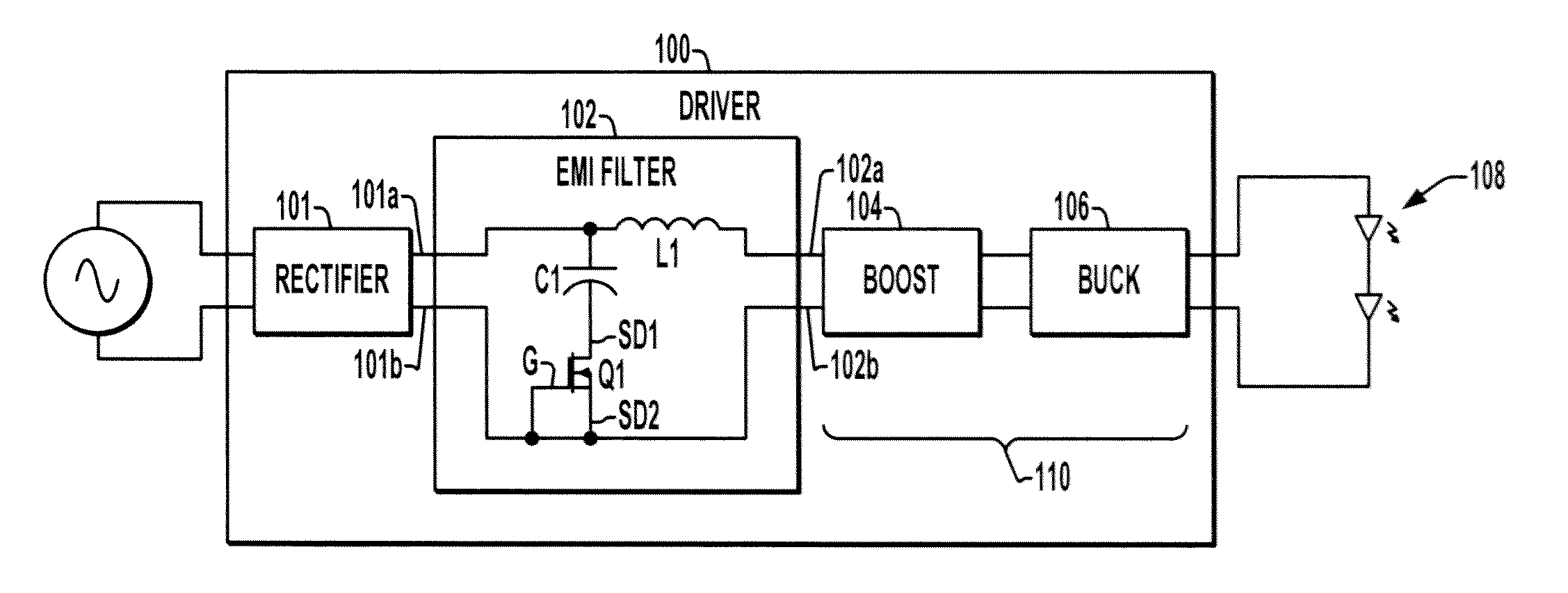
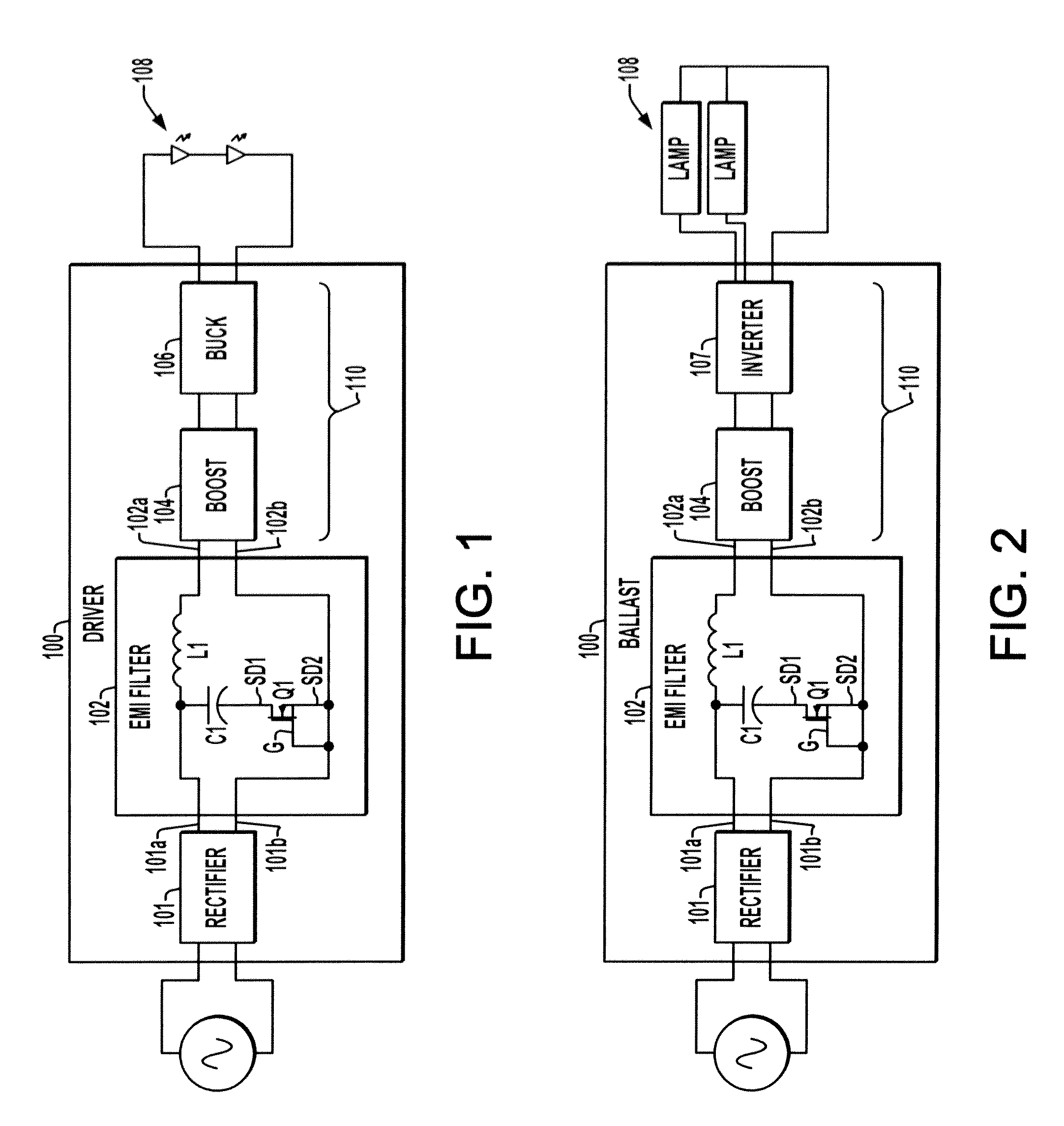
[0014]Referring now to the drawings, like reference numerals are used to refer to like elements throughout and the various features are not necessarily drawn to scale. FIGS. 1 and 2 illustrate two exemplary electronic circuits 100 for powering lighting devices. These power circuits 100 each include an input rectifier 101 receiving signal or multi-phase AC input power from an external source, as well as an EMI filter 102 coupled to the DC side of the rectifier 101. The rectifier circuit 101 in certain embodiments is a full wave rectifier type, including four diode rectifiers formed into abridge circuit for single-phase inputs, or 6 or more rectifiers for multi-phase inputs. In other embodiments, the rectifier circuit 101 can be a half-wave rectifier or a single diode.

[0015]The circuits 100 of FIGS. 1 and 2 also include a power converter circuit 110 including one or more DC to DC converters for directly or indirectly powering at least one light source 108. In the example of FIG. 1, th...


PUM


Abstract

Light e power circuits and EMI filters therefor are presented in which a depletion mode field effect transistor is connected in series with an EMI filter capacitor following an input rectifier to allow filtering of EMI and to limit capacitive currents during triac switching when powered through a phase-cutting dimmer circuit.

Description

BACKGROUND OF THE DISCLOSURE[0001]Conventional electronic power circuits for lighting systems often employ filter circuits with an inductor in a positive DC branch and a capacitor connected across the DC output terminals of an input rectifier to operate as a low pass filter. This filter circuit inhibits the high frequency electromagnetic interference (EMI) caused by power conversion switching from reaching the power line. These devices may be used conjunction with triac-equipped wall or table-top dimmer circuits connected in line with the electronic ballast or LED driver. Such dimmers provide so-called “phase cut” dimming capability where a portion of the line AC waveform is essentially removed in each AC cycle to reduce the light output.[0002]Integral electronic lamps such as compact fluorescent designs (CFLs) and LED lamps can be used in conventional lamps designed for incandescent bulbs and may include dimming circuitry allowing the light output to be adjusted by phase-cut dimmin...

Claims


Application Information

Patent Timeline
Patent Type & Authority Applications(United States)
IPC IPC(8): H05B37/02H05B44/00
CPCH02M1/15H02M1/44H05B41/3921H05B33/0806H03H1/0007H05B45/355H05B45/37H05B45/31H05B45/36H05B45/00
Inventor NERONE, LOUIS ROBERT
Owner GE LIGHTING SOLUTIONS LLC
Why Eureka
Try Eureka