Bleeder circuit and control method thereof, and LED control circuit

a control method and circuit technology, applied in the field of power electronic, can solve the problems of power consumption, surge current generation at the input terminal, and large voltage change rate, and achieve the effect of enhancing system efficiency and reducing power consumption of the bleeder

Active Publication Date: 2018-05-17
JOULWATT TECH INC LTD
View PDF1 Cites 51 Cited by
  • Summary
  • Abstract
  • Description
  • Claims
  • Application Information

AI Technical Summary

Benefits of technology

[0022]Compared with the prior art, using the circuit structure and method of the present disclosure has the following advantages: the present disclosure is applied in an LED control circuit of TRIAC dimming, directly or indirectly detects cross-zero point of input voltage; after the input voltage cross-zero point is delayed by a second time, the bleeder module works to generate bleeder current, and a time between turn-on time of a TRIAC dimmer and a time that a driving circuit input current achieves a predetermined value (maintaining current of the TRIAC dimmer) is a first time. During the first time, the bleeder circuit generates losses; when the first time is greater than a predetermined value, the second time is prolonged; when the first time is smaller than the predetermined value, the second time is reduced, such that the first time is close to or equal to the predetermined value. By using the present disclosure, the second time, which is used as the delay time, is self-adaptively adjusted according to the first time and the predetermined value, and the bleeder power consumption is reduced and system efficiency is enhanced.

Problems solved by technology

However, when the LED lamps replace incandescent lamps, since when the TRIAC is turned on, the voltage at its output terminal will have great voltage change rate (dv / dt), great surge current will be generated at the input terminal.
The surge current has great shock amplitudes, and the duration time is short, easy to cause erroneous turning-off of TRIAC, affect the stable work of the LED driving circuit, make the LED lamp flicker; in addition, the input current of the TRIAC device needs to be greater than its maintaining current; when the input current is smaller than the maintaining current, it is easy to turn off TRIAC, which also causes the flickering of the LED.
Moreover, the bigger the turning-on angle of the TRIAC dimmer is, the longer time t1 that the bleeder circuit generates the bleeder current iblr is, and the bigger the power consumption is, the lower the conversion efficiency is.

Method used


Image

  • Bleeder circuit and control method thereof, and LED control circuit
  • Bleeder circuit and control method thereof, and LED control circuit
  • Bleeder circuit and control method thereof, and LED control circuit

Examples


Embodiment Construction

[0038]The following will describe in great detail the preferred embodiments of the present disclosure by combining the accompanying drawings, but the present disclosure is not limited to these embodiments. The present disclosure covers any replacement, amendment, equivalent methods and solutions made within the sprits and scopes of the present disclosure.

[0039]In order to make the public to thoroughly understand the present disclosure, the following details are described in detail in the preferred embodiments of the present disclosure, and those skilled in the art may totally understand the present disclosure without the descriptions of these details.

[0040]The present disclosure will be described in detail by way of example in the following paragraphs. It needs to be explained that the accompanying drawings all use simplified forms and use non-accurate ratios, and are merely for describing the objectives of the embodiments of the present disclosure conveniently and clearly.
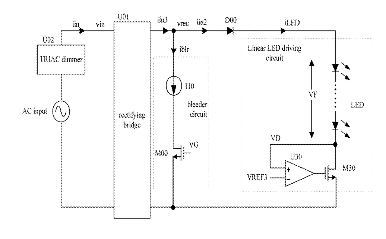
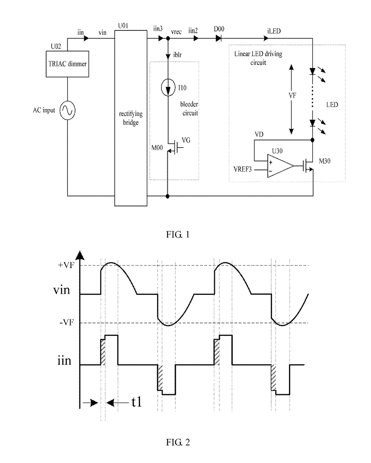
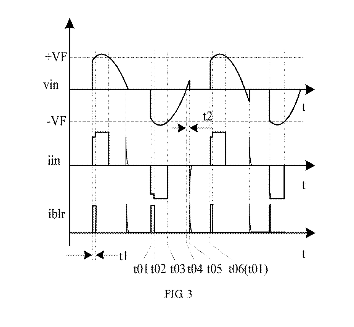
[0041]FIG...


PUM


Abstract

The present disclosure discloses a bleeder circuit and a control method thereof, and an LED control circuit. The present disclosure is applied in an LED control circuit of TRIAC dimming, directly or indirectly detects cross-zero point of input voltage; after cross-zero point of the input voltage is delayed by a second time, the bleeder module works to generate bleeder current, and a time between turn-on time of the TRIAC and a time that a driving circuit input current achieves a predetermined value (maintaining current of TRIAC) is a first time. During the first time, the bleeder circuit generates losses; when the first time is greater than a predetermined value, the second time is prolonged; when the first time is smaller than the predetermined value, the second time is reduced, such that the first time is close to or equal to the predetermined value. By using the present disclosure, the second time, which is used as the delay time, is self-adaptively adjusted according to the first time and the predetermined value, and the bleeder power consumption is reduced and system efficiency is enhanced.

Description

FIELD OF THE INVENTION[0001]The present disclosure relates to the technical field of power electronic, more particularly, to a bleeder circuit and a control method thereof, and an LED control circuit.BACKGROUND OF INVENTION[0002]LED lamps are more energy-saving and environment friendly than traditional fluorescent lamps and incandescent lamps, and thus LED lamps are replacing the current fluorescent lamps and incandescent lamps. In incandescent lamps with a TRIAC dimmer, it is also expected to be replaced by LED lamps, and thus LED needs a compatible TRIAC dimmer. However, when the LED lamps replace incandescent lamps, since when the TRIAC is turned on, the voltage at its output terminal will have great voltage change rate (dv / dt), great surge current will be generated at the input terminal. The surge current has great shock amplitudes, and the duration time is short, easy to cause erroneous turning-off of TRIAC, affect the stable work of the LED driving circuit, make the LED lamp f...

Claims


Application Information

Patent Timeline
Patent Type & Authority Applications(United States)
IPC IPC(8): H05B33/08H05B44/00
CPCH05B33/0845H05B33/0812H05B33/0815H05B45/37H05B45/3575H05B45/395H05B45/10
Inventor LIU, GUOQIANGWONG, PITLEONGREN, YUANCHENGZHOU, XUNWEI
Owner JOULWATT TECH INC LTD
Why Eureka
Try Eureka