Dimmer output emulation

a technology of output emulation and dimming, applied in the field of electronic devices, can solve the problem that the current isub>dim /sub>can prematurely drop below the holding current value h

Inactive Publication Date: 2013-10-29
SIGNIFY HLDG BV
View PDF160 Cites 52 Cited by
  • Summary
  • Abstract
  • Description
  • Claims
  • Application Information

AI Technical Summary

Problems solved by technology

However, when the lamp 122 draws a small amount of current iDIM, the current iDIM can prematurely drop below the holding current value HC before the supply voltage VSUPPLY reaches approximately zero volts.

Method used


Image

  • Dimmer output emulation
  • Dimmer output emulation
  • Dimmer output emulation

Examples


Embodiment Construction

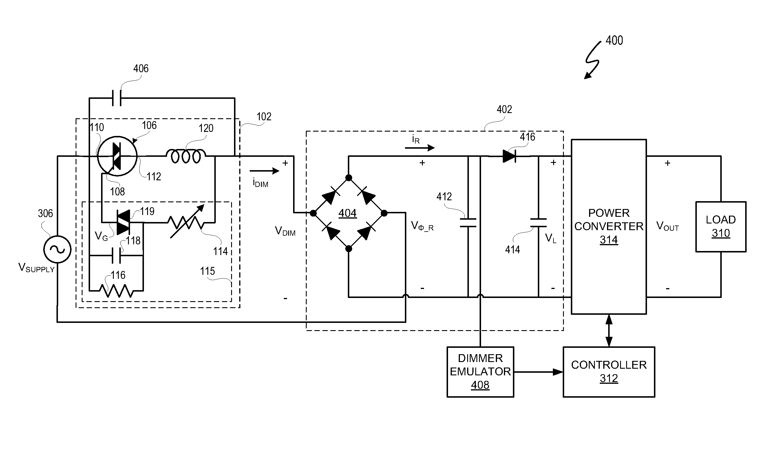
[0027]In at least one embodiment, a lighting system includes a dimmer output voltage emulator to cause a power converter interface circuit to generate an emulated dimmer output voltage. In at least one embodiment, the emulated dimmer output voltage corresponds to an actual dimmer output voltage but is unaffected by non-idealities in the dimmer output voltage, such as premature shut-down of a triac-based dimmer. By generating an emulated dimmer output voltage, the energy delivered to a load, such as a lamp, corresponds to a dimming level setting.

[0028]In at least one embodiment, the power converter interface circuit interfaces with a triac-based dimmer circuit. In at least one embodiment, the dimmer output voltage emulator causes the power converter interface circuit to emulate the output voltage of the triac-based dimmer circuit after the triac in the triac-based dimmer begins conducting. In at least one embodiment, the lighting system draws too little current to allow the triac to ...


PUM


Abstract

A lighting system includes a dimmer output voltage emulator to cause a power converter interface circuit to generate an emulated dimmer output voltage. In at least one embodiment, the emulated dimmer output voltage corresponds to an actual dimmer output voltage but is unaffected by non-idealities in the dimmer output voltage, such as premature shut-down of a triac-based dimmer. By generating an emulated dimmer output voltage, the energy delivered to a load, such as a lamp, corresponds to a dimming level setting.

Description

CROSS-REFERENCE TO RELATED APPLICATION[0001]This application claims the benefit under 35 U.S.C. §119(e) and 37 C.F.R. §1.78 of U.S. Provisional Application No. 61 / 369,202, filed Jul. 30, 2010, and entitled “LED Lighting Methods and Apparatuses” and is incorporated by reference in its entirety.BACKGROUND OF THE INVENTION[0002]1. Field of the Invention[0003]The present invention relates in general to the field of electronics, and more specifically to method and system for dimmer output emulation.[0004]2. Description of the Related Art[0005]Electronic systems utilize dimmers to direct modification of output power to a load. For example, in a lighting system, dimmers provide an input signal to a lighting system. The input signal represents a dimming level that causes the lighting system to adjust power delivered to a lamp, and, thus, depending on the dimming level, increase or decrease the brightness of the lamp. Many different types of dimmers exist. In general, dimmers use a digital o...

Claims


Application Information

Patent Timeline
Patent Type & Authority Patents(United States)
IPC IPC(8): H05B37/02H05B44/00
CPCH05B33/0815H05B33/0848H05B33/0845H05B45/14H05B45/10H05B47/10H05B45/3725H05B45/37
Inventor MELANSON, JOHN L.
Owner SIGNIFY HLDG BV
Why Eureka
Try Eureka