
MMIC DC-to-DC converter

a dc-to-dc converter and converter technology, applied in the direction of dc-dc conversion, power conversion systems, instruments, etc., can solve the problems of large negative, large die space on the integrated circuit, and the possibility of d-mesfet being disabled or powered down, so as to improve power efficiency and start-up reliability, the effect of reducing the die area

Inactive Publication Date: 2005-11-03
AL KURAN SHIHAB +1
View PDF2 Cites 139 Cited by
  • Summary
  • Abstract
  • Description
  • Claims
  • Application Information

AI Technical Summary

Benefits of technology

"The invention is an improved DC-to-DC converter that includes a differential oscillator, synchronous rectifier, and start-up circuit. The oscillator has cross-coupled inductors that increase the effective inductance, allowing for the use of smaller inductors and reducing noise. The synchronous rectifier has MESFET transistors that operate synchronously with the oscillator, increasing efficiency. The start-up circuit prevents voltage from increasing beyond the threshold voltage of a Schottky diode and limits the voltage at the gates of the transistors to allow for successful start-up of the oscillator. Overall, the invention improves the efficiency and reliability of the converter."

Problems solved by technology

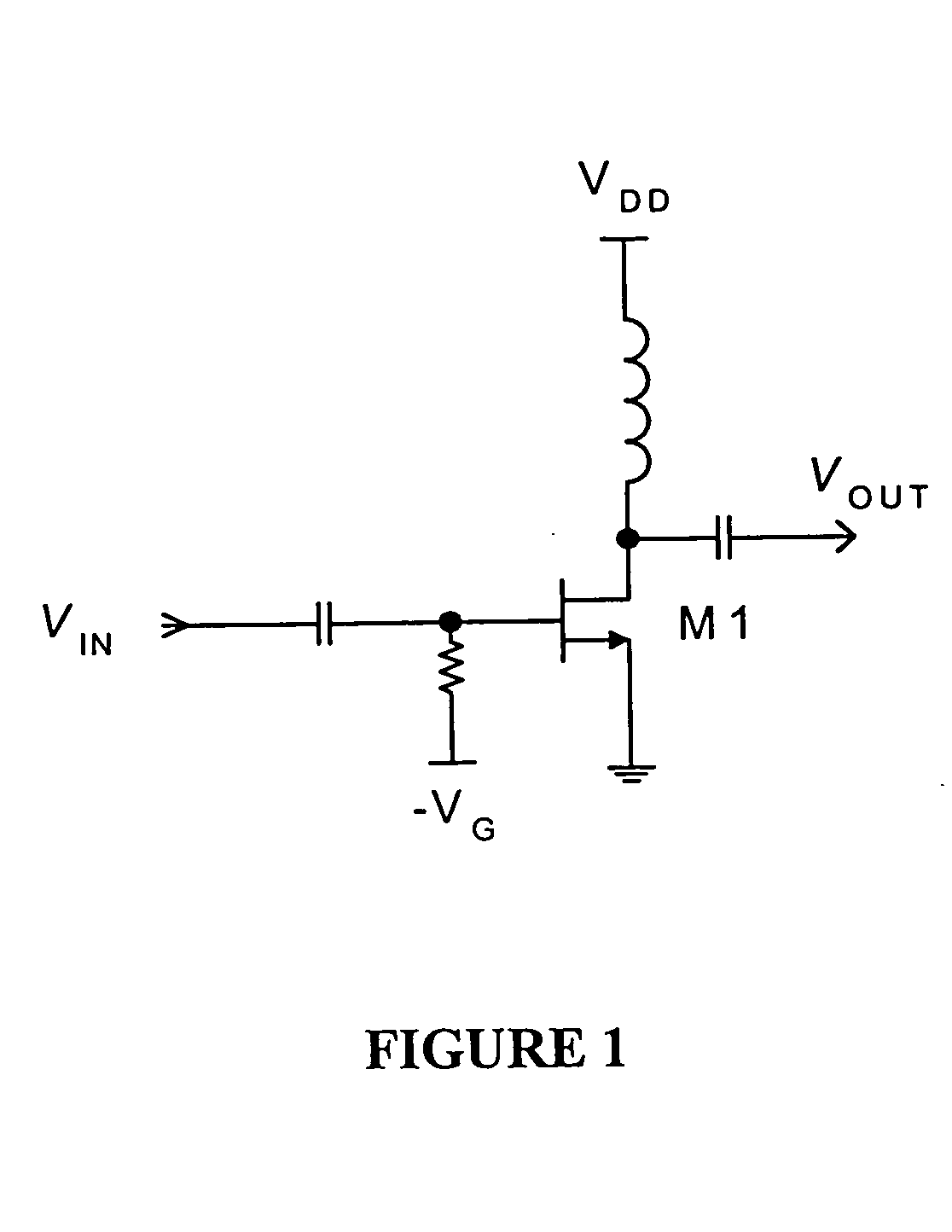
Further, a D-MESFET may be disabled or powered down—e.g., to save power and extend battery life—by making the magnitude of the negative bias voltage—VG relatively large.
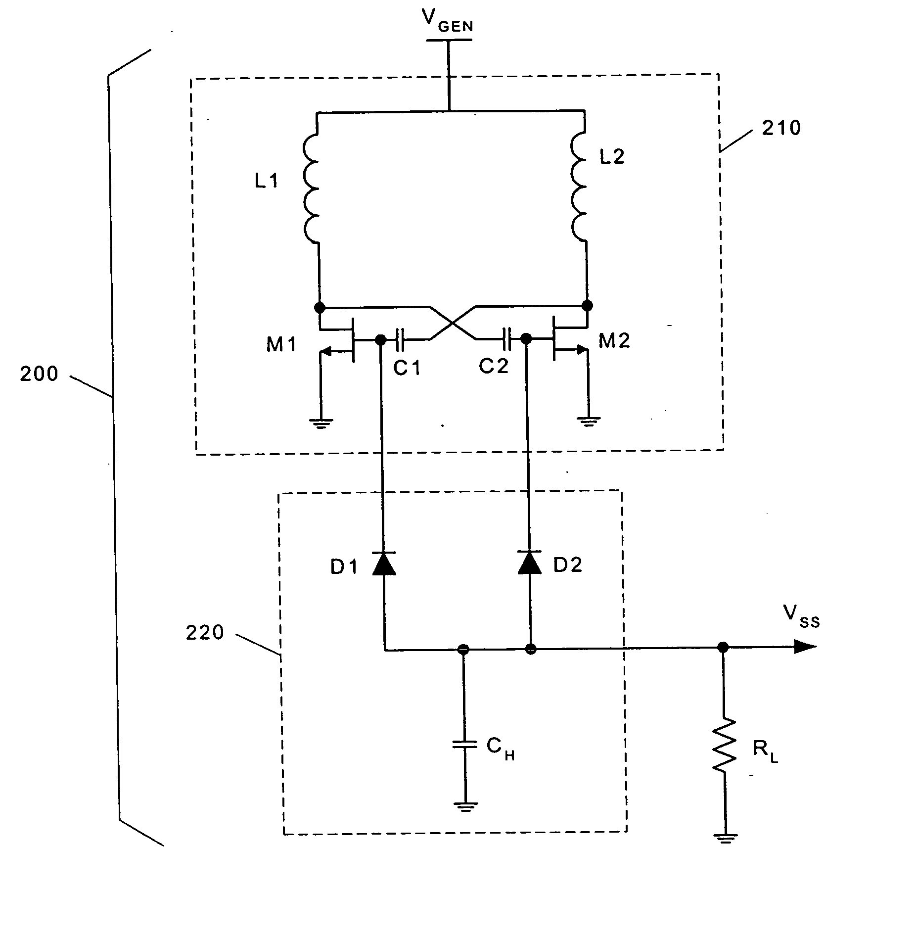
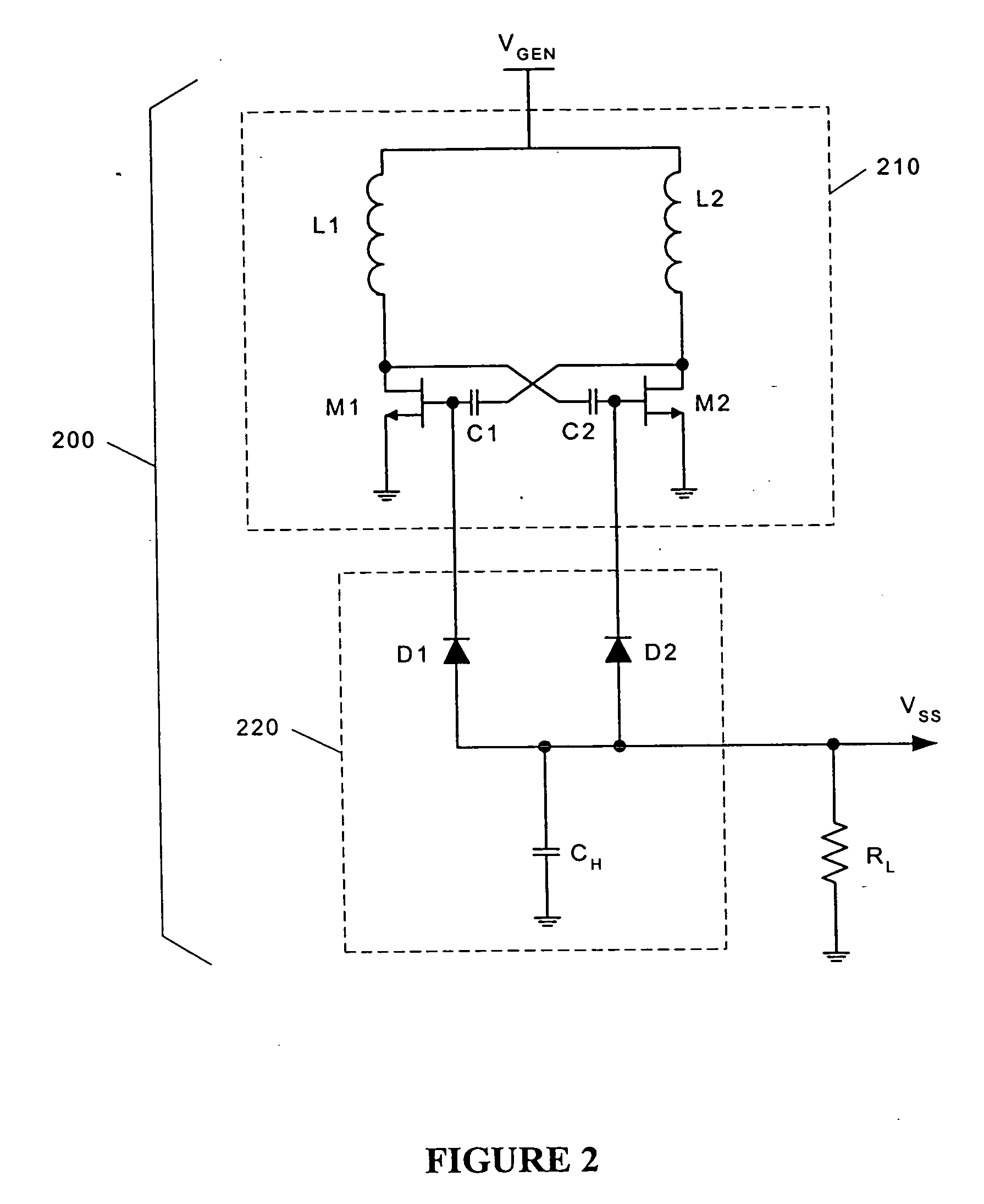
First, symmetric inductors L1 and L2, which are traditionally manufactured on the MMIC as single-plane, spiral-wound inductors, require a relatively large amount of die space on the integrated circuit.
Second, the voltage drop across diodes D1 and D2 reduces the magnitude of the negative DC output voltage VSS and thereby reduces the efficiency of the DC / DC voltage conversion.

Method used


Image

  • MMIC DC-to-DC converter
  • MMIC DC-to-DC converter
  • MMIC DC-to-DC converter

Examples


Embodiment Construction

[0018] With reference to FIG. 3, a microwave DC-to-DC negative voltage converter 300 in accordance with the present invention comprises differential oscillator 310, rectifier 320, and startup circuit 330. Differential oscillator 310, like the prior art differential oscillator 210 described above, comprises inductors L1 and L2, transistors M1 and M2, and capacitors C1 and C2, which are connected in the well-known transistor astable multivibrator configuration. In the present invention, however, inductors L1 and L2 are cross-coupled, interleaved spiral conductors of the type described in U.S. Pat. No. 5,892,425 to Kuhn et al. and shown in FIG. 4. The spiral conductors are arranged in the same plane on the substrate and connected to voltage supply VGEN and transistors M1 and M2 in such a way that inductors L1 and L2 are mirror images of each other. This configuration allows nearly perfect symmetry of the two inductors, which enables such a highly-balanced circuit operation that even-or...


PUM


Abstract

An improved Monolithic Microwave Integrated Circuit DC-to-DC voltage converter fabricated in GaAs MESFET technology is introduced. The converter comprises a differential oscillator having crossed-coupled symmetrical inductors that ensure low-noise operation. The converter further comprises a highly-efficient synchronous rectifier and a start-up enable circuit.

Description

FIELD OF THE INVENTION [0001] The present invention relates to DC-to-DC voltage conversion, and, more particularly, to a high-efficiency, low-noise DC-to-DC negative voltage converter that may be produced on a monolithic microwave integrated circuit (“MMIC”). BACKGROUND OF THE INVENTION [0002] The past two decades have been characterized by the growth in popularity of hand-held communication devices operating at microwave frequencies. Typically, these devices are powered by a battery that provides only a positive DC voltage at a single voltage level. Since various circuit components require different voltage levels to function properly, DC-to-DC voltage converters are necessary for these devices. [0003] Presently, the technology of choice for hand-held communication devices is monolithic microwave integration. The best performance is obtained using Depletion-type Metal-Semiconductor Field Effect Transistors (“D-MESFETs”) on a Gallium-Arsenide (“GaAs”) substrate. The high current den...

Claims


Application Information

Patent Timeline
Patent Type & Authority Applications(United States)
IPC IPC(8): G05F1/40H02M3/156H02M3/158
CPCH02M3/1584H02M3/1563
Inventor AL-KURAN, SHIHABSHEINBERG, NORMAN
Owner AL KURAN SHIHAB
Learn More