Pumping device

a technology of pumping device and pumping shaft, which is applied in the direction of rotary clutches, gearings, fluid couplings, etc., can solve the problems of reducing maintenance requirements, reducing the total of the necessary space requirement of the transportation vehicle, and reducing the redundant mechanical multi-gear transmission between the drive motor and the pump

Inactive Publication Date: 2015-12-24
VOITH PATENT GMBH
View PDF6 Cites 126 Cited by
  • Summary
  • Abstract
  • Description
  • Claims
  • Application Information

AI Technical Summary

Benefits of technology

[0011]The hydrodynamic converter has a cooling circuit for cooling of the operating fluid, typically oil. This cooling circuit can be connected with the cooling circuit of the drive motor and / or the cooling circuit of the engine of the transportation vehicle. The required cooling performance can thereby be better adjusted to the requirements. The design of the individual cooling circuits can moreover be smaller, so that the sum total of the necessary space requirement on the transportation vehicle is reduced. In one advantageous embodiment of the invention, the hydrodynamic converter can also have a separate cooling circuit and can be operated independently.
[0012]In an additional advantageous embodiment of the invention, the drive motor can be an electric drive motor. By using an electric drive motor in combination with a hydrodynamic converter, use of a frequency converter can be foregone. In combination with a guide vane adjustment, the engine characteristics can be expanded.

Problems solved by technology

The use of a hydrodynamic converter also renders a mechanical multi-gear transmission between the drive motor and pump redundant.
Moreover, a vibration decoupling of pump motor and pump occurs, leading to an extension of the operating life of all components and to a reduction in maintenance requirements.

Method used


Image

  • Pumping device
  • Pumping device

Examples


Embodiment Construction

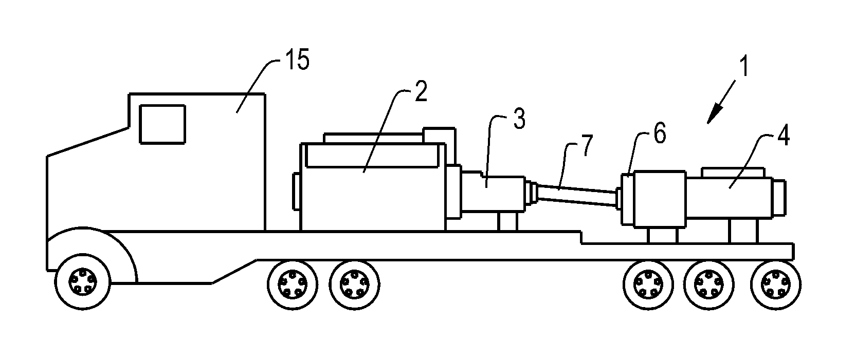
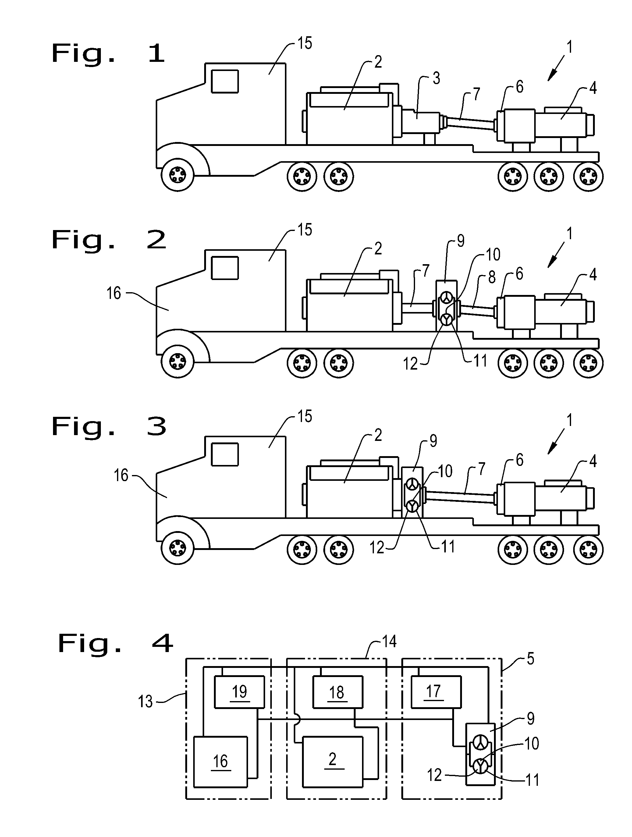
[0019]FIG. 1 shows a pumping device 1 according to the current state of the art. Pumping device 1 includes a pump motor 2, an automatic transmission 3, and a pump 4. Pump 4 is connected via a cardan shaft 7 with automatic transmission 3, whereby pump 4 may have an additional integrated transmission 6.

[0020]FIGS. 2 and 3 show a pumping device 1 with a hydrodynamic converter 9 according to the invention. Pumping device 1 is arranged on a transport vehicle 15 having a separate drive unit 16. The designs in FIGS. 2 and 3 essentially differ in that the converter 9 in FIG. 2 is not flange mounted directly on drive motor 2, but is instead connected via a drive shaft 7 with the drive motor 2.

[0021]With hydrodynamic converters or also hydrodynamic transmissions according to the Fottinger principle the power transfer between pump and turbine wheel occurs through the inertia force of the operating fluid. The stationary guide wheel hereby absorbs the difference which occurs depending upon opera...


PUM


Abstract

The invention relates to a pumping device for introduction of a fluid into a base layer, in particular into a base layer containing gas, for the production of gas-permeable structures in the base layer. The pumping device is arranged on a transportation vehicle having a separate drive unit, including a pump motor and a pump, whereby a speed/torque converter is arranged between pump and pump motor. A hydrodynamic device, in particular a hydrodynamic converter, is used in place of a transmission for speed/torque conversion.

Description

BACKGROUND OF THE INVENTION[0001]1. Field of the Invention[0002]The invention relates to a pumping device for introduction of a fluid into a base layer, in particular into a base layer containing gas, for the production of gas-permeable structures in the base layer, wherein the pumping device is arranged on a transportation vehicle having a separate drive unit.[0003]2. Description of the Related Art[0004]Shale gas is obtained through “hydraulic fracturing,” often referred to as “fracking”. To allow base layers to deliver the gas it is necessary that the base layers possess cracks through which the gas can escape. To produce artificial cracks, guide bores are created through which then a fluid is forced into the surrounding base layer under very high pressure (up to 1500 bar), so that gas permeable structures are produced all around the drill string. The fluid, referred to as “frac fluid,” consists generally of water, sand, and chemicals. As a rule the pumping devices thus employed a...

Claims


Application Information

Patent Timeline
Patent Type & Authority Applications(United States)
IPC IPC(8): F16H41/24F16H41/30
CPCF16H41/30F16H41/24F16H41/28
Inventor HERMANN, ANDREASMIDDELMANN, VOLKERKERNCHEN, REINHARDSCHIRLE, HANS
Owner VOITH PATENT GMBH
Why Eureka
Try Eureka