Method and system for providing local converters to provide maximum power point tracking in an energy generating system

a technology of energy generating system and local converter, which is applied in the direction of power conversion system, dc-dc conversion, instruments, etc., can solve the problems of mppt for the array as a whole being more complicated, drastic power production drop, and inability to provide accurate mppt techniques

Active Publication Date: 2011-06-28
NAT SEMICON CORP
View PDF74 Cites 134 Cited by
  • Summary
  • Abstract
  • Description
  • Claims
  • Application Information

AI Technical Summary

Problems solved by technology

Although MPPT for the entire array is relatively easy to perform when the array is operating under ideal conditions (i.e., the same irradiance, temperature and electrical features for each panel in the array), when there are mismatches or partially shaded conditions, MPPT for the array as a whole is more complicated.
In this situation, MPPT techniques may not provide accurate results due to relative optima of the multi-peak power-to-voltage characteristics of the mismatched array.
This causes a drastic drop in power production because, for an array that includes strings of panels, the least efficient panel in a string determines the current and efficiency for the entire string.

Method used


Image

  • Method and system for providing local converters to provide maximum power point tracking in an energy generating system
  • Method and system for providing local converters to provide maximum power point tracking in an energy generating system
  • Method and system for providing local converters to provide maximum power point tracking in an energy generating system

Examples


Embodiment Construction

voltage variation with time for the system of FIG. 9 in accordance with one embodiment of this disclosure;

[0016]FIG. 11 illustrates the activator of FIG. 9 in accordance with one embodiment of this disclosure; and

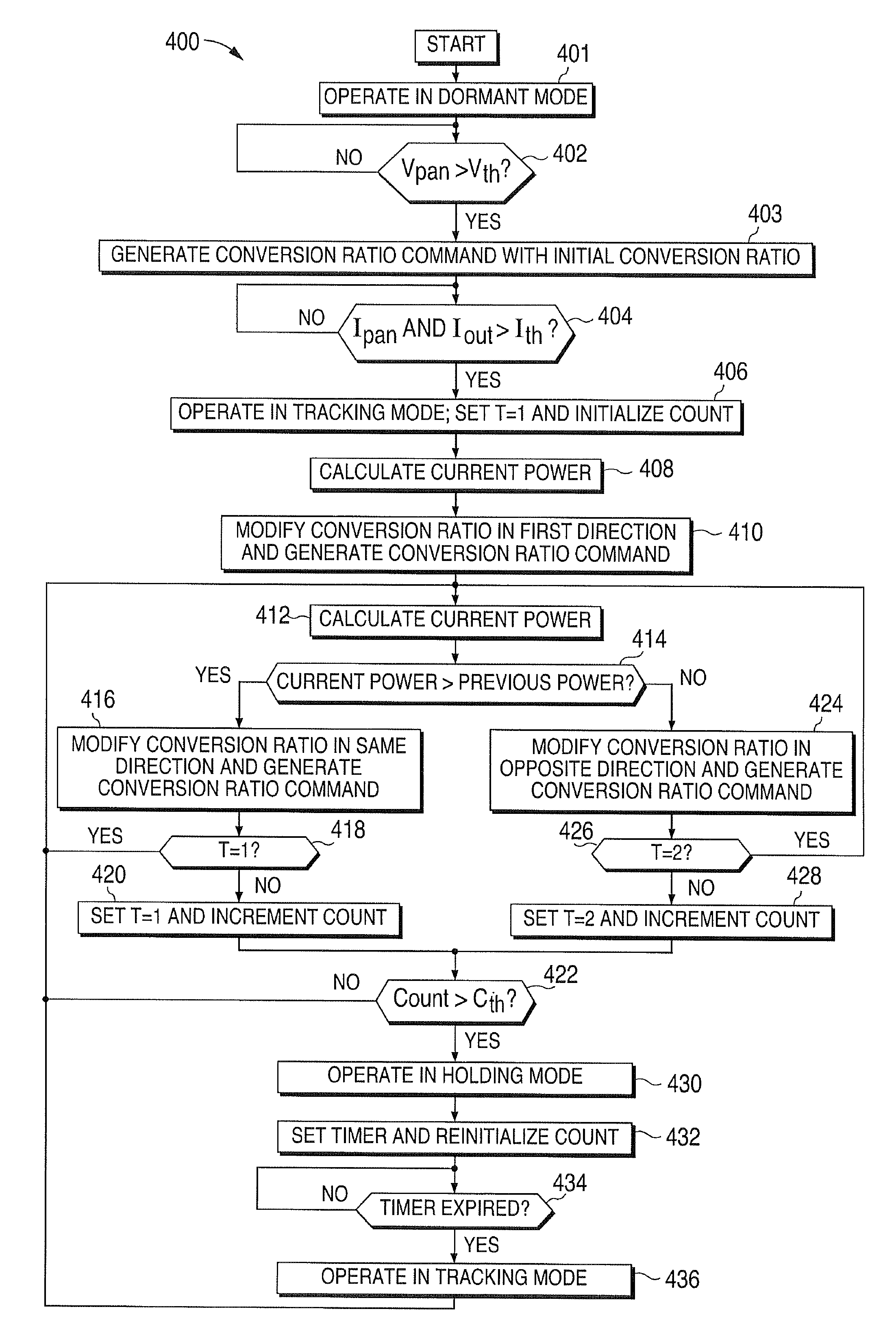
[0017]FIG. 12 illustrates a method for activating and deactivating the local converter of FIG. 9 in accordance with one embodiment of this disclosure.

DETAILED DESCRIPTION

[0018]FIGS. 1 through 12, discussed below, and the various embodiments used to describe the principles of the present invention in this patent document are by way of illustration only and should not be construed in any way to limit the scope of the invention. Those skilled in the art will understand that the principles of the present invention may be implemented in any type of suitably arranged device or system.

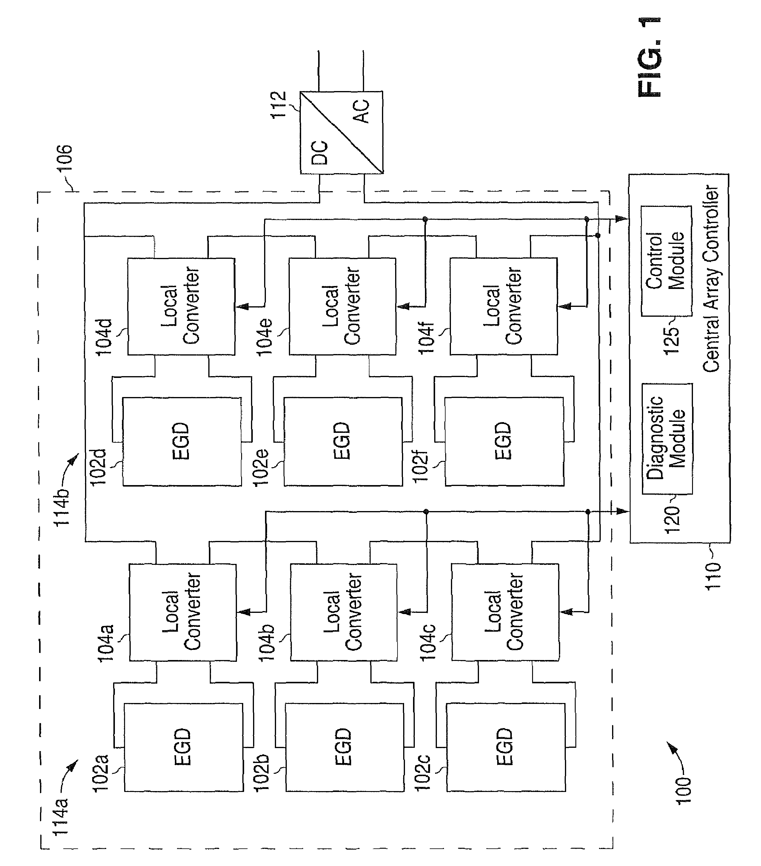
[0019]FIG. 1 illustrates an energy generating system 100 capable of being centrally controlled in accordance with one embodiment of this disclosure. The energy generating system 100 comprises a plura...


PUM


Abstract

A method for providing maximum power point tracking for an energy generating device using a local buck-boost converter coupled to the device is provided. The method includes operating in a tracking mode, which includes initializing a conversion ratio for the buck-boost converter based on a previous optimum conversion ratio. A device power associated with the initialized conversion ratio is calculated. The conversion ratio is repeatedly modified and a device power associated with each of the modified conversion ratios is calculated. A current optimum conversion ratio for the buck-boost converter is identified based on the calculated device powers. The current optimum conversion ratio corresponds to one of a buck mode, a boost mode and a buck-boost mode for the buck-boost converter.

Description

CROSS-REFERENCE TO RELATED APPLICATIONS[0001]The present application is related to U.S. patent application Ser. No. 12 / 152,479 entitled “METHOD AND SYSTEM FOR PROVIDING CENTRAL CONTROL IN AN ENERGY GENERATING SYSTEM,” U.S. patent application Ser. No. 12 / 152,566 entitled “METHOD AND SYSTEM FOR SELECTING BETWEEN CENTRALIZED AND DISTRIBUTED MAXIMUM POWER POINT TRACKING IN AN ENERGY GENERATING SYSTEM,” and U.S. patent application Ser. No. 12 / 152,478 entitled “METHOD AND SYSTEM FOR ACTIVATING AND DEACTIVATING AN ENERGY GENERATING SYSTEM,” all filed concurrently herewith. These patent applications are assigned to the assignee of the present application. The subject matter disclosed in each of these patent applications is hereby incorporated by reference into the present disclosure as if fully set forth herein.TECHNICAL FIELD[0002]This disclosure is generally directed to energy generating systems. More specifically, this disclosure is directed to a method and system for providing local con...

Claims


Application Information

Patent Timeline
Patent Type & Authority Patents(United States)
IPC IPC(8): G05F1/00
CPCG05F1/67H02M3/1582
Inventor ZHANG, JIANHUIDJABBARI, ALILISI, GIANPAOLO
Owner NAT SEMICON CORP
Why Eureka
Try Eureka