Power converter with capacitive energy transfer and fast dynamic response

a technology of capacitive energy transfer and power converter, applied in the direction of electric variable regulation, process and machine control, instruments, etc., can solve the problems of reducing overall efficiency, relative slowness of high-voltage blocking devices, etc., and achieve fast transient response, high power density, and high power density.

Active Publication Date: 2012-07-03
MASSACHUSETTS INST OF TECH
View PDF11 Cites 141 Cited by
  • Summary
  • Abstract
  • Description
  • Claims
  • Application Information

AI Technical Summary

Benefits of technology

[0011]A converter circuit and related technique for providing high power density power conversion includes a reconfigurable switched capacitor transformation stage coupled to a magnetic converter (or regulation) stage. One objective of the circuits and techniques described herein is to provide high power density power conversion circuits which convert an input voltage to an output voltage. In some cases, the circuit converts input voltages to output voltages which are lower than the input voltages and with a fast transient response. In some cases, the circuits and techniques can achieve high performance over a relatively wide input voltage range. This type of converter can be used to power logic devices in portable battery operated applications, for example, which often experience wide input voltage ranges. In other cases it may be desirable to operate the power converter circuit so as to provide a relatively wide range of output voltages. This type of converter could be used to power digital circuits with dynamic voltage scaling, or for supplying power to polar RF power amplifiers, for example, where wide output voltage ranges are commonly required.
[0012]Conventional (e.g. magnetic-based) power converters must typically employ semiconductor switches that are rated for voltages similar in size to the input voltage. These relatively high-voltage blocking devices are inherently slower than lower-voltage devices, and suffer from a higher on-state resistance or larger gate capacitance which both reduce overall efficiency. It would thus be desirable to have a converter that provides high efficiency and fast regulation of the output over a wide input voltage range. Such a converter that combines the strengths of the SC techniques (ease of integration, light-load performance) with the high efficiency and good regulation of conventional switched-mode power converters would be a significant improvement over conventional designs.
[0017]In another aspect, the transformation stage and regulation stage each include two or more switches. The switches in the regulation stage are selected to operate at a switching frequency which is higher than the switching frequency of the switches in said transformation stage. This benefits the efficiency, power density and control bandwidth of the converter. For a given switching frequency at small size scales, the power density of a switched capacitor converter can be much higher than that of a magnetic converter. Moreover, a (low-voltage) magnetic converter stage can be efficiently switched at a much higher frequency than a (high-voltage) switched capacitor converter stage. Thus, operating the SC transformation stage at low frequency and operating the magnetic regulation stage at high frequency provides the best combination of system efficiency and power density. Moreover, as the switching frequency of the regulation stage sets the overall control bandwidth, increased frequency of the regulation stage as compared to the transformation stage enables provision of fast transient performance while maintaining high efficiency.
[0019]With this particular arrangement, a switched capacitor converter which can provide efficient power conversion at is provided. This switched capacitor converter may provide efficient conversion at one conversion ratio or in other designs at multiple distinct conversion ratios. The high-frequency switching converter runs at a switching frequency far higher than that of the switched-capacitor circuit and recovers the energy that is normally dissipated when charging and / or discharging the capacitors. The high-frequency switched converter can also provide high-bandwidth regulation of the converter system output. The circuit can be configured such that the difference between the input voltage and the sum of the charging capacitor voltages appears across the input terminals of the fast switching converter. Because this voltage is substantially lower than the switched-capacitor circuit input voltage, the auxiliary regulating converter can utilize fast, low-breakdown semiconductor switches that enable fast operation and regulation. By making the apparent input resistance of the auxiliary converter higher than the ESR of the switched-capacitor and the SC circuit semiconductor switch resistances, a majority of the capacitor-charging energy can be recovered. Both of these embodiments allow for a sub 1 V dc output with high-bandwidth control of the output.
[0021]The second embodiment tightly couples a switched capacitor circuit with an auxiliary high-frequency converter (e.g. a low-voltage magnetics based converter). The high-frequency switching converter runs at a switching frequency far higher than that of the switched-capacitor circuit and recovers the energy that is normally dissipated in parasitic resistances when charging and / or discharging the capacitors. The high-frequency switched converter can also provide high-bandwidth regulation of the converter system output. The circuit can be configured such that the difference between the input voltage and the sum of the charging capacitor voltages appears across the input terminals of the fast switching converter. Because this voltage is substantially lower than the switched-capacitor circuit input voltage, the auxiliary regulating converter can utilize fast, low-breakdown semiconductor switches that enable fast operation and regulation. By making the apparent input resistance of the auxiliary converter higher than the equivalent series resistance (ESR) of the switched-capacitor and the SC circuit semiconductor switch resistances, a majority of the energy usually lost in capacitor-charging can be recovered. Both of these embodiments allow for a sub 1 V dc output with high-bandwidth control of the output.
[0024]In one embodiment, the auxiliary converter recovers energy normally dissipated when charging capacitors in said switched capacitor circuit by absorbing an instantaneous difference between stacked capacitor voltages in said switched capacitor circuit and an input voltage or an output voltage of the power converter circuit.

Problems solved by technology

These relatively high-voltage blocking devices are inherently slower than lower-voltage devices, and suffer from a higher on-state resistance or larger gate capacitance which both reduce overall efficiency.

Method used


Image

  • Power converter with capacitive energy transfer and fast dynamic response
  • Power converter with capacitive energy transfer and fast dynamic response
  • Power converter with capacitive energy transfer and fast dynamic response

Examples


Embodiment Construction

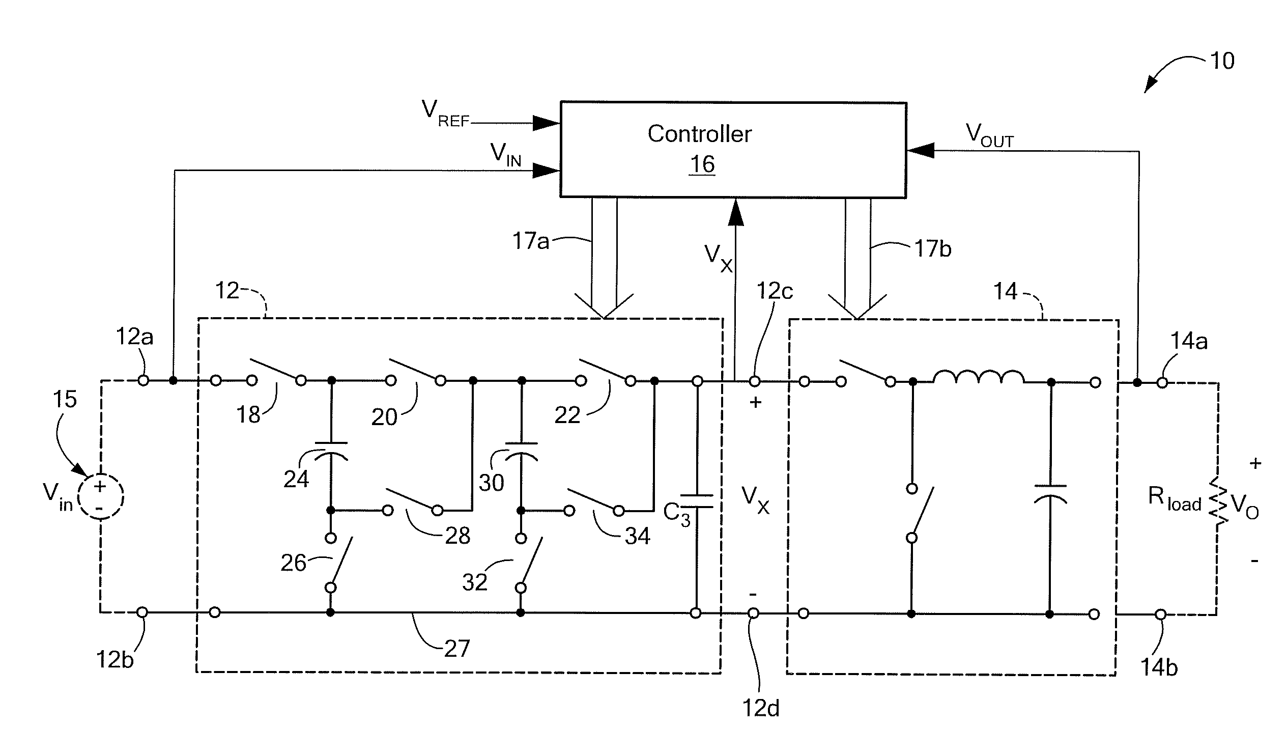
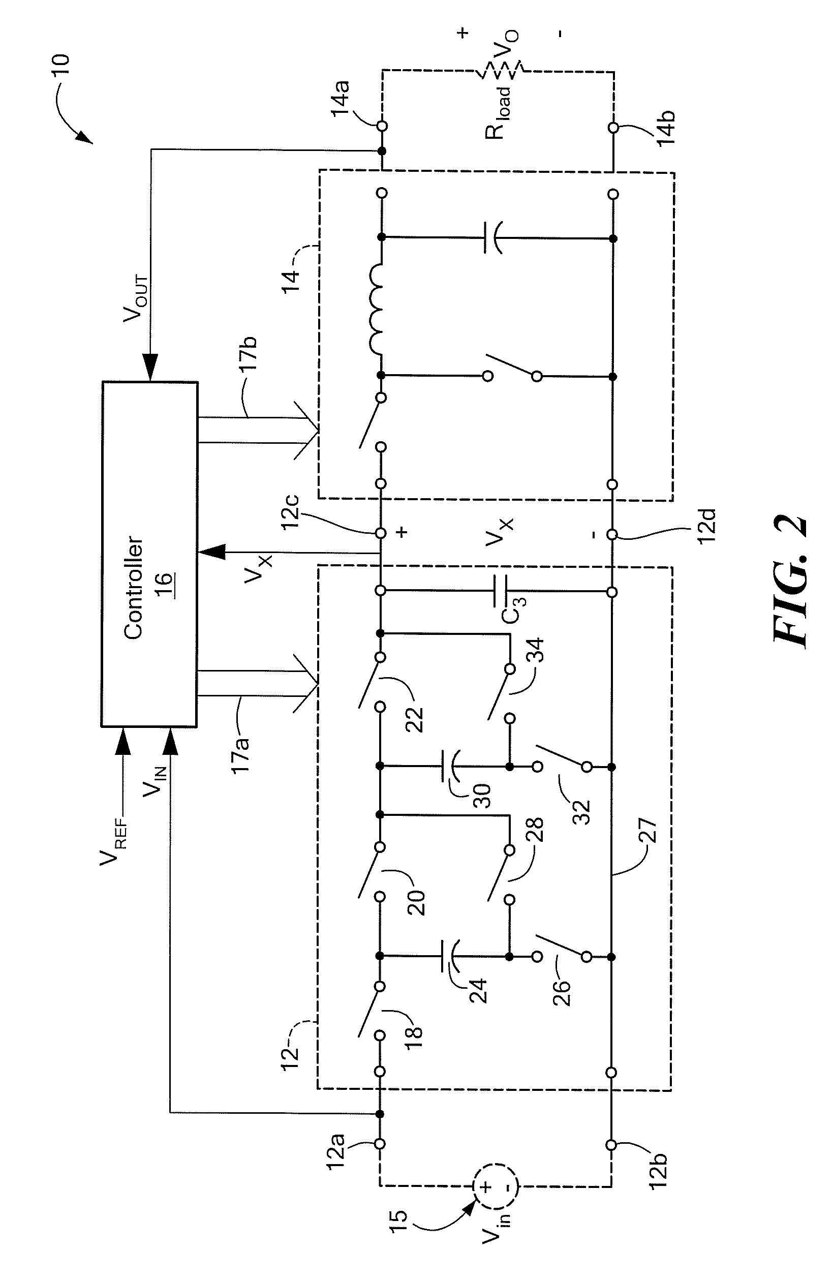
[0042]Before describing several exemplary embodiments of power converter circuits and processing performed by and on such power converter circuits, it should be appreciated that, in an effort to promote clarity in explaining the concepts, reference is sometimes made herein to specific switched capacitor circuits or specific switched capacitor circuit topologies. It should be understood that such references are merely exemplary and should not be construed as limiting. After reading the description provided herein, one of ordinary skill in the art will understand how to apply the concepts described herein to provide specific switched capacitor (SC) circuits or specific switched capacitor circuit topologies. For example, while series-parallel SC topologies may be disclosed herein, such disclosure is provided to promote clarity in the description of the general concepts described herein. After reading the disclosure provided herein those of ordinary skill in the art will appreciate that...


PUM


Abstract

A converter circuit and related technique for providing high power density power conversion includes a reconfigurable switched capacitor transformation stage coupled to a magnetic converter (or regulation) stage. The circuits and techniques achieve high performance over a wide input voltage range or a wide output voltage range. The converter can be used, for example, to power logic devices in portable battery operated devices.

Description

CROSS REFERENCE TO RELATED APPLICATION[0001]This application claims the benefit of U.S. Provisional Application No. 61 / 051,476 filed May 8, 2008 under 35 U.S.C. §119(e) which application is hereby incorporated herein by reference in its entirety.FIELD OF THE INVENTION[0002]The circuits and techniques described herein relate generally to power converters and more particularly to power converters having a capacitive energy transfer and a fast dynamic response.BACKGROUND OF THE INVENTION[0003]The advent of portable electronics and low-voltage digital circuitry has resulted in a need for improved DC-DC converters. DC-DC converters that can provide a low voltage output (<2 V) regulated at high bandwidth, while drawing energy from a higher, wide-ranging input voltage (e.g., typically about a 2:1 range) are particularly useful for supplying battery-powered portable electronics. The size, cost, and performance advantages of integration make it desirable to integrate as much of the DC-DC ...

Claims


Application Information

Patent Timeline
Patent Type & Authority Patents(United States)
IPC IPC(8): G05F1/00
CPCH02M3/07H02M3/155H02M2001/007H02M3/158Y02B70/10H02M1/007
Inventor PERREAULT, DAVID J.PILAWA-PODGURSKI, ROBERT C. N.GIULIANO, DAVID M.
Owner MASSACHUSETTS INST OF TECH
Why Eureka
Try Eureka