Two-stage voltage regulators with adjustable intermediate bus voltage, adjustable switching frequency, and adjustable number of active phases

a voltage regulator and intermediate bus technology, applied in the direction of electric variable regulation, process and machine control, instruments, etc., can solve the problems of insignificant, low internal resistance of batteries, and inability to meet the needs of modern design, so as to increase efficiency and widen the effect of current load variation

Inactive Publication Date: 2006-07-04
VIRGINIA TECH INTPROP INC
View PDF6 Cites 133 Cited by
  • Summary
  • Abstract
  • Description
  • Claims
  • Application Information

AI Technical Summary

Benefits of technology

[0010]It is therefore an object of the present invention to provide a voltage regulator of small dimensions and weight and having increased efficiency while capable of accommodating wide variation in current load and high frequency load transients.
[0011]It is another object of the invention to provide a two-stage voltage regulator wherein the second stage may be of arbitrary design and constitution while the first stage substantially improves overall efficiency of the voltage regulator by providing a variable bus voltage Vbus.
[0012]The present two-stage converter has a first regulator stage, a second regulator stage and a control circuit that controls the first stage. The first stage provides an adjustable intermediate bus voltage Vbus. The second stage receives the bus voltage Vbus and provides an output current. The control circuit responds to the output current, and controls the first stage so that the bus voltage Vbus increases with increasing output current. This arrangement tends to improve the conversion efficiency.
[0013]In a preferred embodiment, a switching frequency of the second stage increases as the bus voltage Vbus increases. This tends to further improve conversion efficiency and maintain a constant output current ripple.
[0014]Also, in the present converter, the second stage can comprise a plurality of regulators (e.g. buck regulator phases) connected in parallel. The number of active (i.e. operating) regulator phases can be increased as output current increases. This tends to further increase conversion efficiency.

Problems solved by technology

However, the amount of power which may be stored in and recovered from batteries is necessarily limited, particularly where the size or weight of the batteries must be limited for convenience of the use of the device.
The internal resistance of batteries, while low in modern designs, is not negligible and also causes voltage reduction with increased load.
Unfortunately, circuits capable of regulating voltage, even with relatively wide tolerances, necessarily consume a finite amount of power since the output voltage must necessarily be reduced from a higher voltage by causing a voltage drop across some components in the voltage regulator while a current is being supplied.
However, transient changes in load current may cause corresponding fluctuations in the regulator output voltage unless the voltage is adequately filtered, generally requiring a relatively large storage capacitor or voltage regulation from a higher voltage with a correspondingly larger voltage drop so that peak currents can be supplied from the voltage regulator or a combination of both; either of which necessarily requires features which are generally undesirable in a portable device (e.g. the size and weight of filter capacitors and the increased inefficiency of the voltage regulator coupled with increased battery size and weight to compensate for that inefficiency).
These interrelated problems are particularly acute in regard to portable data processing devices such as laptop computers and similar device alluded to above.
The duration of operation for each use cycle is generally a significant fraction of an hour, at a minimum, while digital processing, memory and logic circuits required therein require extremely close tolerances of voltage regulation, size and weight constraints are severe for commercially competitive designs and, most importantly, the changes in load current are particularly large, especially in modern processor designs with sophisticated power saving circuits.
Thus, at the present state of the art, the voltage regulator may consume an amount of power comparable to that required, on average, by the processor and is thus a significant factor in battery life and a significant limitation on the period of usability of the laptop computer or other portable digital device per battery charge while the efficiency of the voltage regulator is generally comparatively lower than for many other devices in view of the close regulation required and the wide variation in loads which must be accommodated.

Method used


Image

  • Two-stage voltage regulators with adjustable intermediate bus voltage, adjustable switching frequency, and adjustable number of active phases
  • Two-stage voltage regulators with adjustable intermediate bus voltage, adjustable switching frequency, and adjustable number of active phases
  • Two-stage voltage regulators with adjustable intermediate bus voltage, adjustable switching frequency, and adjustable number of active phases

Examples


Embodiment Construction

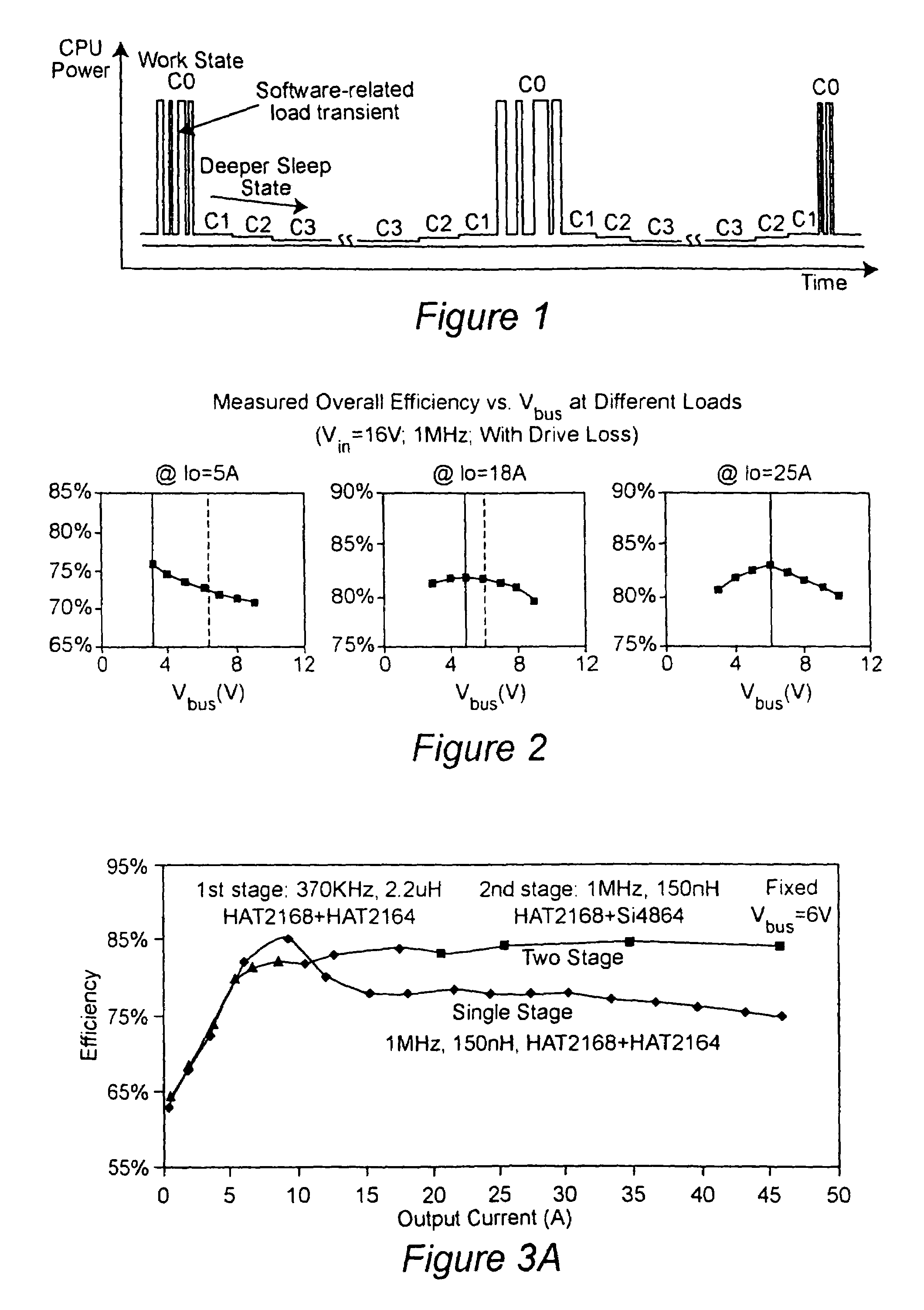
[0037]Referring now to the drawings, and more particularly to FIG. 1, there is shown a graphical representation of an exemplary power consumption pattern for a digital processor through several cycles which each include a plurality of operating states C0, C1, C2 and C3. Operating state C0 is the working state in which the processor is performing data processing operations at the full clock rate. This working state is generally characterized by a plurality of peaks or high plateaus of processing operations interspersed with relatively lower levels of processing and power consumption as may be caused by the software controlling the operations of the processor. The working state periods are generally fairly brief and of variable duration (also dependent upon software) and are usually widely separated (generally due to at least the time required for a user to assimilate the information content of a display of the results of operations during a C0 working period and to provide a further ...


PUM


Abstract

A two-stage power converter that dynamically adjusts to output current requirements includes a first stage regulator that provides power to a second stage regulator. The first stage can be a buck converter, and the second stage can be a multiple-phase buck converter. The output voltage of the first stage (intermediate bus voltage Vbus) is varied according to the load current to optimize conversion efficiency. To provide maximum efficiency, the Vbus voltage is increased as load current increases. The Vbus voltage provided by the first stage can be varied by duty cycle or operating frequency control. In another embodiment, the switching frequency of the second stage is varied as output current changes so that output current ripple is held constant. In an embodiment employing a multiple-phase buck converter in the second stage, the number of operating phases are varied as output current changes.

Description

CROSS-REFERENCE TO RELATED APPLICATIONS[0001]This application is a continuation-in-part (CIP) application of U.S. patent application Ser. No. 10 / 781,931 filed Feb. 20, 2004, the complete contents of which is herein incorporated by references, and benefit of the priority date thereof is hereby claimed.DESCRIPTIONBACKGROUND OF THE INVENTION[0002]1. Field of the Invention[0003]The present invention generally relates to high efficiency electrical power supply voltage regulators and, more particularly to improving the efficiency of voltage regulators which must supply power to highly variable loads with extremely wide variation in current requirements.[0004]2. Description of the Prior Art[0005]All electrically operated devices require electrical power and are designed to operate on the type of power which can be provided from the source which is most convenient in view of the intended function. Devices which are generally operated in a fixed location, such as household appliances and oth...

Claims


Application Information

Patent Timeline
Patent Type & Authority Patents(United States)
IPC IPC(8): H02M3/158G05F1/40H02M3/156
CPCH02M3/156H02M2001/0019Y02B70/16H02M2001/007H02M2001/0032H02M1/0019H02M1/0032H02M1/007Y02B70/10
Inventor XU, MINGZHOU, JINGHAIREN, YUANCHENGLEE, FRED C.WEI, JIA
Owner VIRGINIA TECH INTPROP INC
Why Eureka
Try Eureka