Flat roof solar racking system

a solar racking and flat roof technology, applied in the direction of climate sustainability, furniture parts, coupling device connections, etc., can solve the problems of not being able to address all of these concerns, the spacing between rows of solar panels is not well established, and the majority of left unusabl

Active Publication Date: 2012-09-27
SOLAR MOUNTING SOLUTIONS
View PDF18 Cites 60 Cited by
  • Summary
  • Abstract
  • Description
  • Claims
  • Application Information

AI Technical Summary

Benefits of technology

[0021]It is a further object of the present invention to provide a solar panel racking system which does not require modification to a flat roof on which it is disposed.

Problems solved by technology

Many commercial buildings have flat roofs and most are left unused.
However, none of the prior art systems are designed to be capable of addressing all of these concerns.
The spacing between rows of solar panels is not well established and therefore requires guesswork during installation.
As the spacing is not well established, rows of solar panels may not be laid out optimally.
The mounting system also does not allow solar panels to be installed all at once after mounting system has been fully erected.
Such mounting system also prevents easy access to wiring of solar panels and cannot be disassembled easily for roof repair.
Such mounting system lacks the consideration of air flow or circulation around the solar panels for cooling purposes.
The spacing between rows of solar panels is also not well established and therefore requires guesswork during installation.
Further, the spacing between solar panels is also not well established.
As the spacing is not well established, solar panels may not be laid out optimally on a given surface area.
In addition, it also requires adding a hole to each solar panel frame, thereby risking voiding the solar panels' manufacturer warranties.
Judging from the parts disclosed, this mounting system appears to not be fully grounded as a rubber pad separates the mounting system from the roof and no grounding connections are observed to fully ground the mounting system.
In addition, it also requires adding a hole to each solar panel frame, thereby risking voiding the solar panels' manufacturer warranties.
Further, this mounting system incorporates moving parts to accommodate unusual wind forces which increase the need for periodic maintenance.

Method used


Image

  • Flat roof solar racking system
  • Flat roof solar racking system
  • Flat roof solar racking system

Examples


Embodiment Construction

[0115]As used herein, the terms “grounding” or “ground” shall be construed to mean electrically grounding (“ground”) an object or bonding the object to a ground potential. As used herein, the term “bonding” means permanently joining to form an electrically conductive path that ensures electrical continuity and that the formed bond has the capacity to safely conduct any current likely to be imposed. The term “about” is used herein to mean approximately, roughly, around, or in the region of. When the term “about” is used in conjunction with a numerical range, it modifies that range by extending the boundaries above and below the numerical values set forth. In general, the term “about” is used herein to modify a numerical value above and below the stated value by a variance of 20 percent up or down (higher or lower).

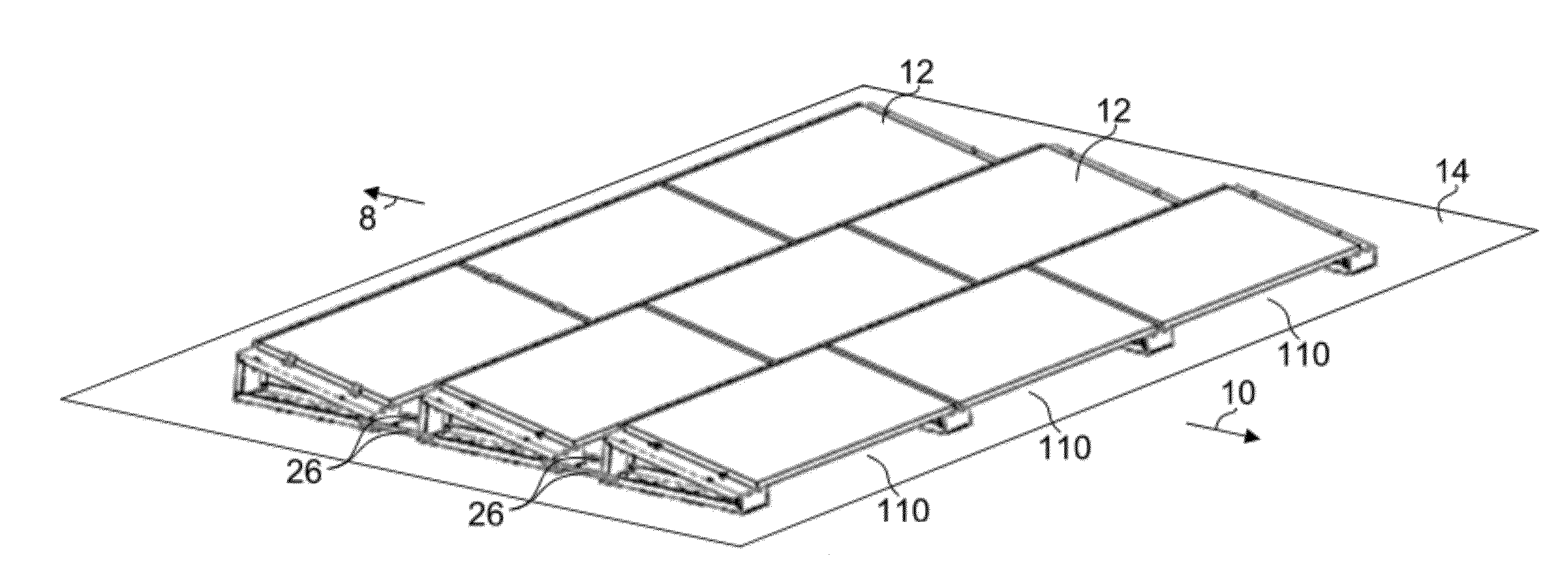
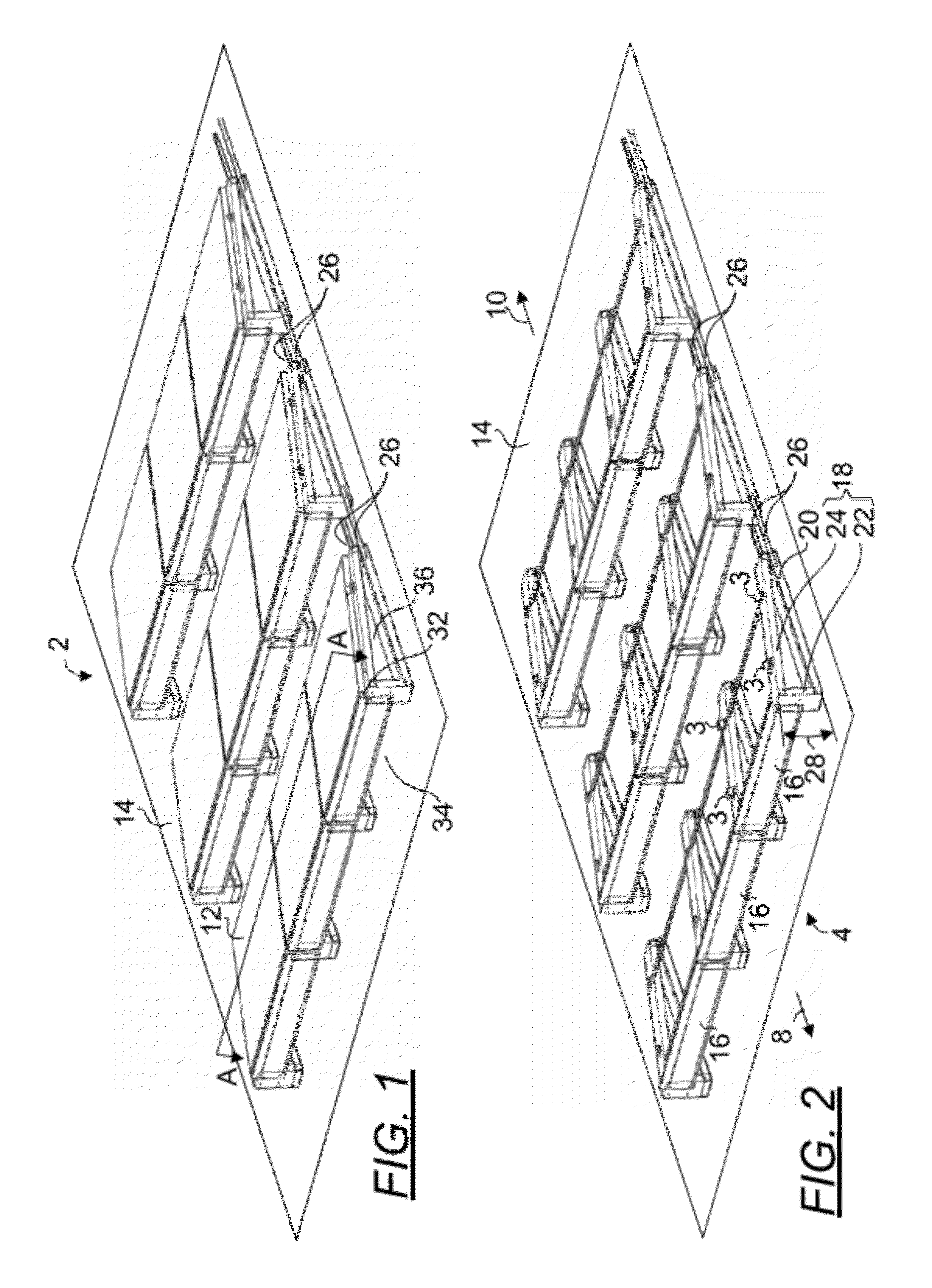
[0116]FIG. 1 is a top front perspective view of a solar panel array 2 disposed on a flat roof 14 utilizing the present racking system 4. FIG. 2 is a top front perspective v...


PUM


Abstract

A flat roof racking system configured for receiving solar panels having electrically conductive frames, the racking system comprising substantially parallelly disposed panel support structures, spacer bars and retaining and grounding clips pairs, each panel support structure comprises a first end, a second end, a top member having a first channel section connected to a second channel section and two ends, and a bottom member having a channel section and two ends. The first and second channel sections are disposed in a plane but at an angle from one another and each end of the bottom member is fixedly connected to an end of the top member such that the top member is configured to make a first tilt angle at the first end with the bottom member and a second tilt angle at the second end with the bottom member.

Description

RELATED APPLICATIONS AND PRIORITY CLAIM[0001]This application claims priority to provisional application U.S. Ser. No. 61 / 467,245 filed Mar. 24, 2011. Said application is incorporated by reference herein in its entirety.BACKGROUND OF THE INVENTION[0002]1. The Field of the Invention[0003]The present invention is directed generally to a racking system for securing solar panels, and in particular, to a racking system for securing solar panels disposed on a flat roof.[0004]2. Background Art[0005]Recent advancements in solar cell technology and skyrocketing fossil fuel prices have prompted many businesses to consider solar energy as an alternative energy source. Many commercial buildings have flat roofs and most are left unused. These large expanses of flat spaces present ideal opportunities to place solar panels as they are typically not publicly accessible and free from significant natural debris such as leaves or shade cast by trees or buildings.[0006]As labor costs are high, it is im...

Claims


Application Information

Patent Timeline
Patent Type & Authority Applications(United States)
IPC IPC(8): E04D13/18
CPCF24J2/4638F24J2/5233F24J2/5239H02S20/24Y02E10/47Y02B10/20Y02B10/12F24J2/5258F24S40/85F24S2025/6008F24S25/16F24S25/13F24S25/636Y02E10/50Y02B10/10
Inventor RIVERA, ANGEL M.MAYER, STANLEY E.
Owner SOLAR MOUNTING SOLUTIONS
Why Eureka
Try Eureka