3-Dimensional Displaying Apparatus And Driving Method Thereof

a technology of displaying apparatus and driving method, which is applied in the direction of optics, electrical apparatus, instruments, etc., can solve the problems of pseudo-stereoscopic vision, observer cannot see normal 3-dimensional stereoscopic information, and cannot observe clear 3-dimensional images, so as to prevent pseudo-stereoscopic vision and minimize the change of image information brightness

Active Publication Date: 2012-09-27
SAMSUNG ELECTRONICS CO LTD
View PDF9 Cites 14 Cited by
  • Summary
  • Abstract
  • Description
  • Claims
  • Application Information

AI Technical Summary

Benefits of technology

[0015]The present disclosure is directed to providing a non-glasses 3-dimensional displaying apparatus and its driving method, which may ...

Problems solved by technology

However, the method for displaying 3-dimensional images by means of parallax separation by the parallax barrier plate 130 has several problems to be solved.
As a result, a clear 3-dimensional image cannot be observed.
As a result, pseudo-stereoscopic vision is generated so that the observer cannot see normal 3-dimensional stereoscopic informa...

Method used


Image

  • 3-Dimensional Displaying Apparatus And Driving Method Thereof
  • 3-Dimensional Displaying Apparatus And Driving Method Thereof
  • 3-Dimensional Displaying Apparatus And Driving Method Thereof

Examples


first embodiment

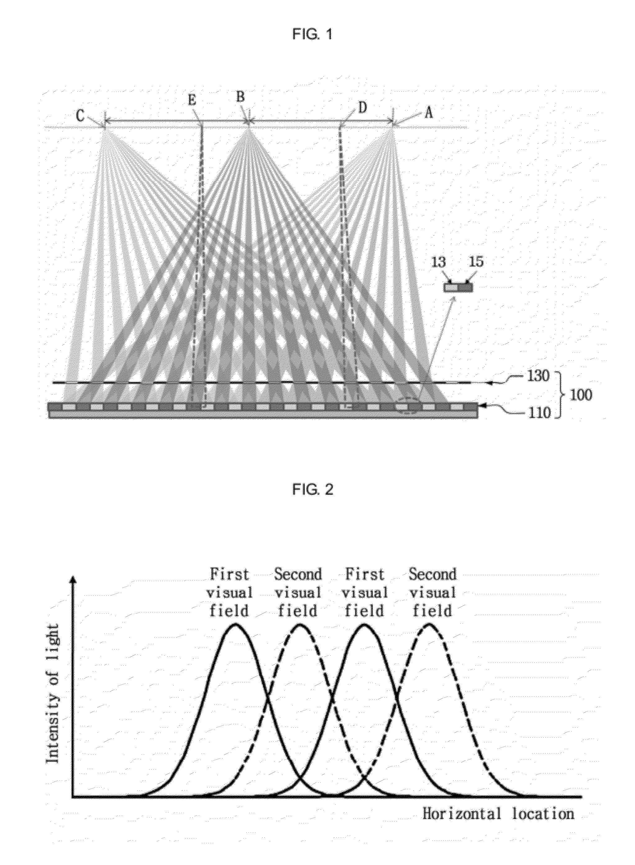
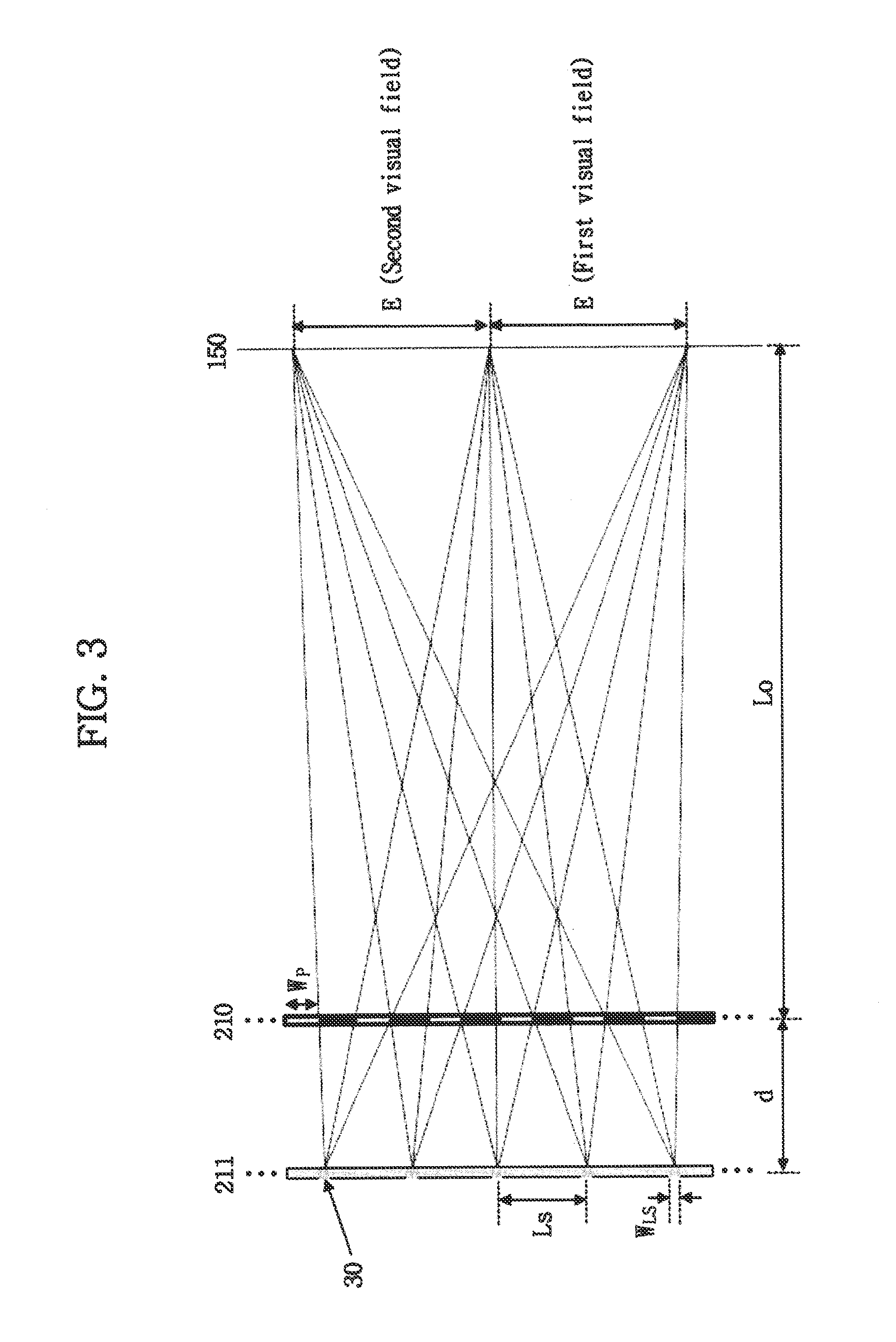
[0049]FIG. 3 shows an autostereoscopic display using a line source according to an embodiment disclosed herein. Referring to FIG. 3, the display of this embodiment includes an image displaying panel 210 and a backlight panel 211 having a plurality of line sources (hereinafter, referred to as a first line source set) arranged spaced apart from the rear surface of the image displaying panel 210 by a predetermined distance. The plurality of line sources of the first line source set 30 of the backlight panel 211 are arranged at regular intervals so that image information formed on the image displaying panel 210 has different visual fields at a designed observing location 150. FIG. 3 shows a concept in which a left visual field (a first visual field) and a right visual field (a second visual field) are separated at the designed observing location for two-visual field image information, as an example.

[0050]The size E of each visual field is based on 65 mm, which is an average distance bet...

second embodiment

[0059]Though the apparatus of the first embodiment allows observing a 3-dimensional image with uniform brightness within a predetermined range when the eyes move in a horizontal direction within the corresponding visual field, it is impossible to entirely eliminate the problem of pseudo-stereoscopic vision and crosstalk when moving between visual fields. The second embodiment disclosed herein is directed to solving the problems of the first embodiment. Also, the techniques about the width of line source described in the first embodiment may be applied to the structure of the second embodiment as it is to control the uniformity of brightness.

[0060]FIG. 7 is a schematic view showing a 3-dimensional displaying apparatus using a plurality of line sources disclosed herein. Referring to FIG. 7, a backlight 211 having line sources arranged spaced apart from each other at regular intervals is disposed at the rear side of an image displaying panel 210, as in the first embodiment disclosed he...

third embodiment

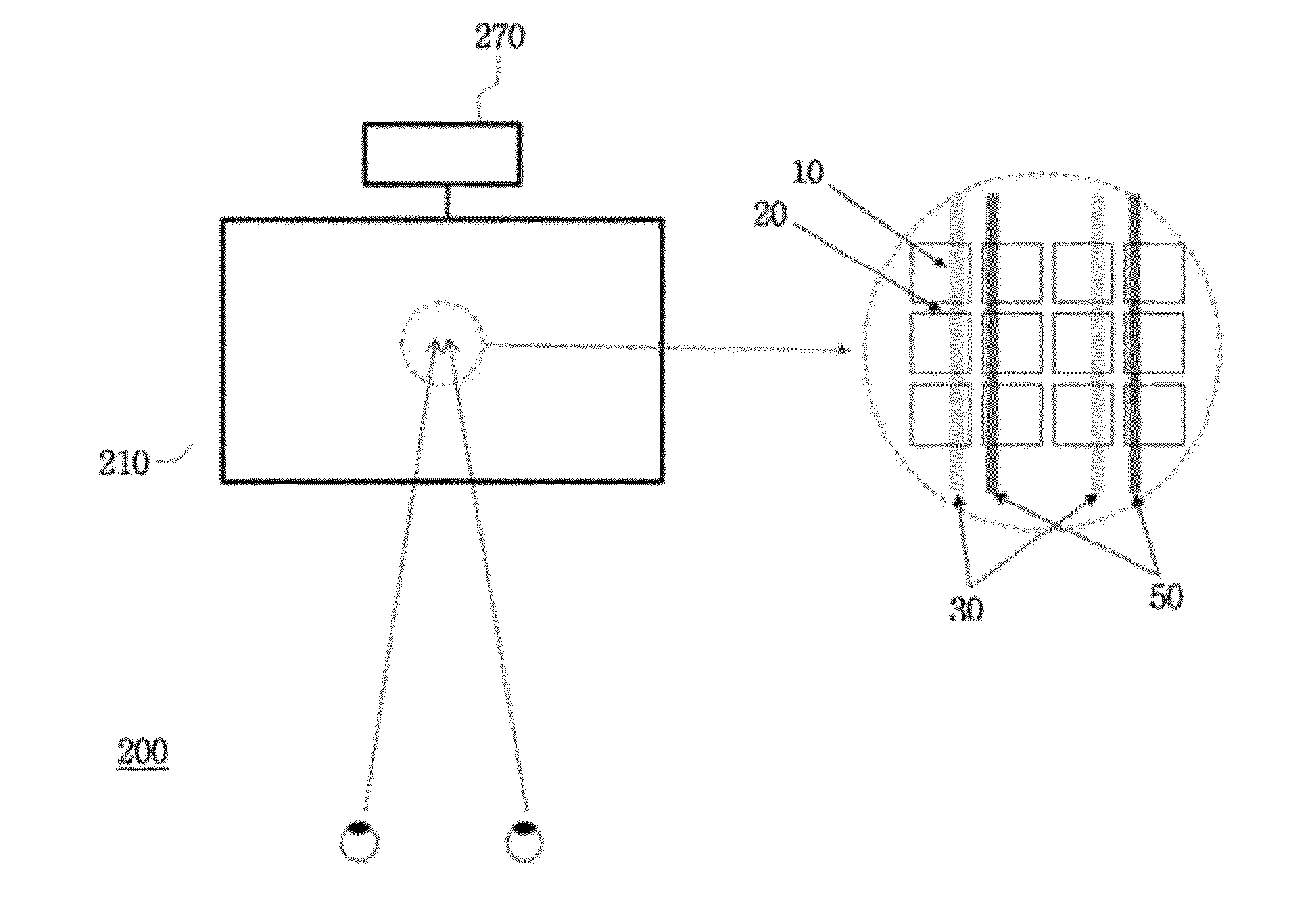
[0065]FIGS. 10 and 11 are enlarged front views showing a 3-dimensional displaying apparatus according to a third embodiment disclosed herein. The pixels shown in FIGS. 8 and 9 are generally composed of red (R), green (G) and blue (B) sub pixels to realize a color image displaying apparatus. As shown in the right side of FIG. 10, the vertical line source set shown in FIGS. 8 and 9 is arranged so that all of the sub pixels R, G and B in the pixel 10 and the first and second line source sets 30 and 50 are arranged in a vertical direction. Thus, in a case where one of the first and second line source sets 30 and 50 is operated, the light emitted from the operating line source set passes through all of the sub pixels R, G and B at each pixel. As a result, no problem occurs in realizing colors while visual fields are separated.

[0066]However, as shown in the right part of FIG. 11, in a case where the sub pixels R, G and B are arranged in a horizontal direction, a color 3-dimesional image m...


PUM


Abstract

A 3-dimensional displaying apparatus includes an image displaying panel having a plurality of pixels and a backlight panel spaced apart from one surface of the image displaying panel. The backlight panel includes a first line source set having a plurality of line sources arranged at regular intervals and a second line source set having line sources arranged spaced apart from the respective line sources of the first line source set by a predetermined interval. The first line source set and the second line source set are driven alternately. Thus, in a case where a horizontal location of an observer varies, the change of brightness of image information and the crosstalk between adjacent visual fields are minimized, and pseudo-stereoscopic vision is prevented. Also, the irregularity of brightness distribution in a visual field may be solved

Description

CROSS-REFERENCE TO RELATED APPLICATION[0001]This application claims priority to Korean Patent Application No. 10-2011-0024939, filed on Mar. 21, 2011, and all the benefits accruing therefrom under 35 U.S.C. §119, the contents of which in its entirety are herein incorporated by reference.BACKGROUND[0002]1. Field[0003]The present disclosure relates to a 3-dimensional displaying apparatus, and more particularly to a 3-dimensional displaying apparatus and a driving method thereof, in which a set of line sources are driven alternately to minimize the change of brightness of image information and crosstalk between adjacent visual fields and to prevent pseudo-stereoscopic vision in a case where a horizontal location of an observer is changed.[0004]2. Description of the Related Art[0005]In recent, to meet the increasing demands on displaying apparatuses capable of realizing 3-dimensional images, which can give substantial stereoscopic views, not available in existing 2-dimensional images, v...

Claims


Application Information

Patent Timeline
IPC IPC(8): G09G5/00G02B27/22G02B30/33
CPCG02B27/2214G09G3/342H04N13/32H04N13/383H04N13/398G09G3/003G09G3/36G09G2320/0209G02B30/33H04N13/00G02B30/27G09G3/22G09G3/3406G09G2320/0233
Inventor KIM, SUNG KYUYOON, KI HYUK
Owner SAMSUNG ELECTRONICS CO LTD
Why Eureka
Try Eureka